Lennox iComfort CBX32MV-06 Setup Manual Download Page 30

507152-01

7/2013

Page 30

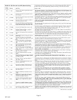
Table 10. Alert Codes and Troubleshooting

Critical alerts are displayed on Home (user) screen, in the Homeowner alert button, and in the
Installer alert button. Minor and Moderate alerts are found only in the Installer alert button.

Alert

Code

Steps to clear

Alert Text

Priority

404

Critical

(Outdoor Unit) The compressor rotor is
locked up. This could be due to a short cir
cuiting of the run capacitor, seizing of the
bearings or excessive liquid refrigerant etc.

Compressor rotor locked up due to run capacitor short, bearings are seized, excessive liquid
refrigerant, etc. (NOTE: May need to install hard start kit). Clears the error after 4 consecutive
normal run cycles or after power reset.

405

Critical

(Outdoor Unit) The compressor circuit is
open. This could be due to a power discon
nection, open fuse etc.

Compressor circuit open (due to power disconnection, open fuse, etc.) Clears the
error after 1 normal compressor run cycle.

406

Critical

(Outdoor Unit) The required amount of cur
rent is not passing through the start current
transformer.

Required amount of current is not passing through Start current transformer. Clears the error
after current is sensed in START sensor, or after power reset.

407

Critical

(Outdoor Unit) The required amount of cur
rent is not passing through run current trans
former.

Required amount of current is not passing through Run current transformer. Clears the error
after current is sensed in RUN sensor, or 1 normal compressor run cycle, or after power reset

408

Critical

(Outdoor Unit) The compressor is running
continuously.

Compressor runs continuously. Clears the error after 1 normal compressor run
cycle or after power reset.

409

Moderate

(Furnace / Air Handler / Outdoor Unit) The
secondary voltage for the 

(furnace, air-hand

ler or outdoor unit)

 has fallen below 18VAC. If

this continues for 10 minutes, the thermostat
will turn off the 

(furnace, air-handler or out

door unit).

Secondary voltage is below 18VAC. After 10 minutes, operation is discontinued.
Clears the code after voltage is higher than 20 VAC for 2 seconds or after power
reset.

410

Moderate

(Outdoor Unit) The outdoor unit pressure is
below the required limit.

Unit pressures are below the lower limit. Pressure switch opens at 40 psig (system shuts down)
and closes at 90 psig (system restarts).

411

Critical

(Outdoor Unit) The low pressure switch has
opened 5 times during one cooling cycle. As
a result, the thermostat has shutdown the
outdoor unit.

Open low pressure switch error count reached 5 strikes. Check system charge using approach
and sub cooling temperatures. Reset by putting outdoor unit control in test mode or resetting
low voltage power.

412

Moderate

(Outdoor Unit) The outdoor unit pressure is
above the required limit. The system will shut
down.

Unit pressure is above the upper limit. System is shut down. The high pressure switch for
HFC410A will open at 590PSIG and close at 418PSIG. Confirm that the system is properly
charged with refrigerant. Check condenser fan motor, TXV, indoor unit blower motor, stuck
reversing valve or clogged refrigerant filter. Confirm that the outdoor unit is clean. The alarm
clears after the pressure switch closes or a power reset

413

Critical

(Outdoor Unit) The high pressure switch has
opened 5 times during one cooling cycle. As
a result, the thermostat has shutdown the
outdoor unit.

Open high pressure switch error count reached 5 strikes. Check system charge
using approach and sub cooling temperatures. Check outdoor fan operation. Check for dirt or
debris blocking air flow to outdoor unit. Reset by putting outdoor unit control in test mode or
resetting low voltage power.

414

Critical

(Outdoor Unit) The discharge line temperat
ure is higher than the recommended upper
limit of 279ºF.

Discharge line temperature is > 279ºF. Make sure coil is clean and airflow unobstructed in and
out of condenser. Check system operating pressures and compare to unit charging charts in
installation manual. Clears after discharge temperature is < 225ºF.

415

Critical

(Outdoor Unit) The discharge line temperat
ure has been consistently higher than the
recommended upper limit of 279ºF.

Discharge line high temperature error count reached 5 strikes. Make sure coil is clean and
airflow unobstructed in and out of condenser. Check system charge using approach and sub
cooling temperatures. Reset by putting outdoor board in test mode or resetting low voltage
power.

416

Critical

(Outdoor Unit) The outdoor coil sensor is
either open, short-circuited or the temperat
ure is out of sensor range. As a result the
outdoor unit control will not perform any de
frost tempering.

Sensor being detected open or shorted, or temperature is out of sensor range.
Outdoor unit control will not perform demand or time/temperature defrost operation. (System
will still heat or cool.) Clears when outdoor unit control detects proper sensor readings.

417

Critical

(Outdoor Unit) The outdoor unit sensor is
either open, short-circuited or the temperat
ure is out of sensor range. As a result the
outdoor unit control will not perform any de
frost tempering.

Outdoor unit control detects open or shorted sensor, or temperature that is out of sensor range.
Critical Alert after 10 minutes. Reset by replacing sensor. This fault is detected by allowing the
unit to run for 90 seconds before checking sensor resistance. If the sensor resistance is not
within range after 90 seconds, the board will count one fault. After 5 faults, the board will lock
out. Check for proper sensor reading and attachment to line. Replace if out-of-specifications.

417

Moderate
/ Critical

(Damper Control Module) The damper con
trol discharge air temperature sensor is either
open, short-circuited or the temperature is
out of sensor range.  As a result the outdoor
unit control will not perform any defrost tem
pering.

The damper control module detects open or shorted discharge sensor, or temperature that is
out of discharge sensor range. Check the resistance of the discharge sensor and compare to
temperature resistance chart - replace if needed.  Reset by replacing the discharge sensor.
This fault is detected by allowing the unit to run for 90 seconds before checking discharge
sensor resistance.  If the discharge sensor resistance is not within range after 90 seconds, the
control will count one fault.  After 5 faults, the control will lock out. Check for proper sensor
reading and attachment to line.  The alarm clears after a power reset.

418

Moderate

(Outdoor Unit) There is a faulty “W” output
circuit.

Faulty W output circuit.

419

Critical

(Outdoor Unit) The “W” output on the outdoor
unit has reported more than 5 errors. As a
result, the system has shutdown the outdoor
unit.

W output hardware fault count reached 5 strikes.

420

Critical

(Air Handler / Equipment Interface Module) )
The heat pump defrost cycle has taken more
than 20 minutes to complete.

Defrost cycle lasts longer than 20 minutes. Check heat pump operation. Cleared
when W1 signal is removed. Applicable only in communicating mode with non-communicating
heat pump.

421

Critical

(Outdoor Unit) The “W” output terminal on the
outdoor unit is not wired correctly.

Voltage sensed on W output terminal when Y1 out is deactivated.

422

Moderate

Compressor  top  cap  switch  exceeding
thermal limit.

Check condenser fan motor, TXV, indoor unit blower motor, stuck reversing valve or clogged
refrigerant filter.  Automatically clears when error is corrected.

423

Moderate  /
Critical

The inverter has detected a circuit problem

.

Control will lockout after 10 strikes within an hour. To clear disconnect power to outdoor unit
and restart.

table continued on next page

Summary of Contents for iComfort CBX32MV-06

Page 1: ... or Auxiliary Dehumidifier 5 Adjusting Equipment Parameters 6 Adjusting Humidification and De humidification Settings with Non Communicating Outdoor Units 11 Adjusting Humidification and De humidification Settings with Communicating Outdoor Units 13 Adjusting Zoning Control Settings 15 Using the Tests Diagnostics Features 17 Connecting to a Home Wi Fi Network 18 Registering the Thermostat 19 Accou...

Page 2: ...oling humidification and De humidification without user involvement OUTDOOR TEMPERATURE SENSOR All Lennox branded communicating outdoor units contain a built in outdoor temperature sensor INSTALLATION AND SETUP COMMUNICATION ERROR SCREEN During initial thermostat start up if the following screen appears see figure 1 this will indicate that the thermostat has been incorrectly wired or has shorted w...

Page 3: ...tatus remotely or receive email alerts when there is a problem no yes WARNING The dealer number is your Lennox account number Enter the entire dealer number including the letters and numbers e A12345 If you do not know your dealer number please contact your Lennox representative Are you sure you want to proceed Figure 5 Dealer Number Warning The following table lists all of the installer configura...

Page 4: ...ot icomfort enabled you must be at the Add or Remove Non communicating equipment screen 1 Press the yes button on this screen see 1 2 In the non communicating device list screen use the arrows 2a to highlight Outdoor Unit Type and press edit 2b 3 Touch one of the radio buttons 3a to select a 1 or 2 Stage AC Unit or a 1 or 2 Stage HP Unit press save 3b 4 Use arrows 4a to highlight any red colored t...

Page 5: ...icating equipment 4a 4b System Heat Pump Furnace Thermostat Bypass 24VAC Humidifier 5b 3a Figure 7 Add Non Communicating Device Humidifier ADDING HUMIDITROL OR AN AUXILIARY DEHUMIDIFIER Before adding a dehumidifier be sure that the dehumidifier is wired to the furnace or air handler control as shown on the Optional Accessories wiring diagram see page 37 the entire system is wired powered up and th...

Page 6: ...ing highlight it then press Edit System 9 39 am Aug 15 2012 edit next back about resetAll Parameter Name Default Parameter Value Setting Increment Equipment Name keyboard input screen Filter 1 Timer Selection Calendar Time Calendar Time Run Time Filter 2 Timer Selection Calendar Time Calendar Time Run Time UV Bulb Timer Selection Calendar Time Calendar Time Run Time Humidifier Pad Timer Selection ...

Page 7: ... Heating 100ºF 100 to 130ºF 5ºF Zoning Target Supply Air Temp for HP Heating 90ºF 85 to 110ºF 1ºF Zoning Supply Air Temp Limit for Cooling 40ºF 35 to 45ºF 2ºF Zoning Supply Air Temp Limit for Gas Electric Heating 140ºF 140 to 160ºF 5ºF Number of stages shown in thermostat is dependent on equipment that is installed Electric heat will bring on 2 elements at a time if available Lock in 2nd stage HP ...

Page 8: ...l Air Handler Parameter Name Default Parameter Value Setting Increment Equipment Name Air Handler keyboard input screen Electric Heating Airflow nnnn CFM See Note at end of table NOTE CFM Default and Values Settings are dependent on the tonnage of the unit 5CFM High Cooling Airflow nnnn CFM See Note at end of table NOTE CFM Default and Values Settings are dependent on the tonnage of the unit 5CFM ...

Page 9: ... Control Type Selections available if discharge air temperature sensor is installed fixed cfm and fixed discharge air temperature Low Heating Airflow Low and high heating air flow is dependent on model of indoor unit High Heating Airflow Gas Heat Airflow Settings Heating Airflow Control Type variable capacity furnaces only 0 Fixed CFM 0 1 1 DATS installed 0 Fixed CFM 1 Fixed DAT Low Heating Airflo...

Page 10: ...p to the closest number on 25 CFM resolution Note 3 All communicating Installer Parameters default CFM values based on DIP switch setting non communicating value are calculated using the CFM conversion tables and rounded up to closest number on 25 CFM resolution Table 7 System Devices Thermostat System Heat Pump Furnace Thermostat system devices To adjust a setting high light it then press Edit ed...

Page 11: ...re 10 Adjust a Non Communicating Device Setting Humidification How Humidification Mode Works DISPLAY BASIC AND PRECISION These modes allow user control of relative humidity between 15 and 45 These conditions must be met for either mode to operate humidification mode has been enabled and the unit is in HEAT mode and humidification demand exists 24V present at H and DISPLAY mode indicates humidifica...

Page 12: ...oint Control Humiditrol Comfort Adjust Min De humidification Setpoint edit reset back De humidification Control Mode current value 45 9 39 am Aug 15 2012 4a 4b Humiditrol Comfort Adjust settings are only available on units equipped with a Humiditrol De humidification device resetAll 2b 6 Min De humidification Setpoint Range is 40 to 60 Default is 45 inc 1 cancel save set to 42 5a 5b returns to adj...

Page 13: ...HUMIDIFICATION DEVICE NOTE OFF MEDIUM and HIGH De humidification modes are also a function of the HVAC system with NO external De humidification devices installed In OFF mode De humidification if off In MEDIUM mode De humidification occurs if these conditions are met and signals are present at specific terminals De humidification has been enabled on installer settings and the unit is in COOL mode ...

Page 14: ...To adjust a setting highlight it then press Edit System reinstall edit reset De humidification Control Mode current value back Midpoint Overcooling Pre adjustment REQUIREMENTS 1st the device has been installed 2nd from the Add or Remove Non communicating equipment press next 3rd in the Adjust a setting screen configure the device as follows 1 In the system devices list use the arrows 1a to highlig...

Page 15: ...r only calls If the blower is required to operate while the auxiliary dehumidifier is running a separate wire must be installed from the auxiliary dehumidifier to the indoor unit s G thermostat input that will energize G when the auxiliary dehumidifier is running see wiring diagram on page 37 Auxiliary De humidification is controlled by the thermostat De humidification demand NOTE Refer to HCWH De...

Page 16: ... furnace about System Furnace Thermostat 2 Stage HP Unit Zoning Control reset All edit System Equipment Name Zoning Target Supply Air Temp C Zoning Target Supply Air Temp fo Zoning Target Supply Air Temper Zoning Target Supply Air Temper Zoning Supply Air Temp Limit for Zoning Supply Air Temp Limit for HP heating lockout time Zoning Target Supply Air temp for Cooling 1 current value edit Zoning Ta...

Page 17: ...tton to un check desired test 2 Press the start button 4 to run all selected tests or press skip tests 5 to end the test procedure 3 After the tests are completed or you have selected skip test select the exit button to end Blower HP Heat 1st Stage HP Heat 2nd Stage Defrost Now Cooling 1st Stage Cooling 2nd Stage Gas Heat 1st Stage Gas Heat 2nd Stage select all select test to run deselect all skip...

Page 18: ...to set temp 75 Heat to 72 heat or cool fan is AUTO enter away outdoor temperature 80 system is cooling Wi Fi Zone 1 1 Wi Fi Figure 24 Press Wi FI 2 Press the Wi Fi enable button WI FIL SETTINGS Press to enable disable Wi FI 9 39 am Aug 15 2012 disabled Thermostat is not connected to the Wi FI network WI FI Wi Fi Zone 1 X Figure 25 Enable Wi FI 3 Press next as many times as necessary then press acc...

Page 19: ...signal strength can be viewed from the thermostat interface Use steps 1 1 Press NETWORK SETTINGS this screen shows a graphical view of buttons representing Wi Fi options OPEN and SECURE wireless networks and a button for adding a network 2 Select the access point that has already been establish and connected too There are two options to select from which are connect and AP info Select AP Info and ...

Page 20: ...with an Internet connection Please complete your Lennox iComfort registration by clicking the link below Register NOTE if the customer has already setup an account click the Click Here button to access that account Click on the Register link the screen to the left will appear Fill in the User Name and Password fields and check the agree to terms and conditions box Click Create User button A series...

Page 21: ...r press cancel equipment diagnostics tests alerts setup 9 39 am Aug 15 2012 EXIT confirm cancel 2 1 3 Figure 35 Re Configuration Process If any component of the HVAC system has been changed e g replacing an outdoor sensor reconfiguring the system will be required To begin reconfiguring a system after you have accessed the program from the Lennox logo previous page press the setup button 1 figure 3...

Page 22: ...ess edit Use arrows to select a temperature between 40 and 55ºF Press save SMOOTH SETBACK RECOVERY SSR SSR is an algorithm designed to smoothly reach a occupied program schedule set point The algorithm looks 2 hours ahead for the occupied program schedule period s set point If the occupied set point requires the system to turn on present temperature below the heat set point or above the cool set p...

Page 23: ...orter to maintain temperature 4 Tempering Variable Capacity Modulating Furnace SLP98 Dual fuel tempering staged furnace employs no sensor implementation Furnace starts heating at minimum heat rate while defrost is active Testing has shown the entering air is within acceptable limits During defrost the airflow will run at second stage CFM Abbreviations FURN auxiliary heat provided by gas furnace HP...

Page 24: ... operation control using the following inputs Room temperature History of cycle times how long does it typically take to bring the room temperature to the desired set point Target set point and Differential temperature settings between 1st 4th stage The thermostat uses this information to vary the heating capacity to efficiently satisfy the heating demand The full range of the furnace heating capa...

Page 25: ...he left side of the system and device alerts screen shows a list of each communicating device discovered in the system and check boxes for selecting each device Or you may use buttons to the right of the System Devices list to select all or deselect all After something has been selected use view active to list all active alerts for selected devices If there are no alerts the display will show Ther...

Page 26: ...r the transformer maybe overloaded and check 24VAC voltage at the DEVICE The alarm is only cleared by pressing the clear button on the Installer Alerts Tab If the fault persists after check ing the connections replace the unit s control board 34 Critical Thermostat The thermostat does not know the capacity tonnage of the furnace air handler or outdoor unit Please program the correct capacity of th...

Page 27: ...t door Unit Equipiment Interface Module Damper Control Module The Thermostat furnace air handler or outdoor unit control parameters are corrupted Reconfigure the system Replace the control if heating or cooling is not available 132 Critical Air Handler Damper Control Module The device s control software is corrupted Recycle power If failure re occurs replace the control System reset is required to...

Page 28: ...off during a heating cycle Check micro amperes of flame sensor using thermostat diagnostics Clean or replace sensor Measure voltage of neutral to ground to ensure good unit ground The alarm fault will clear when a heat call ends successfully 274 Critical Furnace The furnace limit switch has been open for more than 3 minutes The system will go into Watchguard mode Check firing rate and air flow Che...

Page 29: ...tacts did not close or the relay coil in the electric heat section did not ener gize The air handler will operate on 1st stage electric heat until the issue is re solved Heat section Stage 3 failed Same as Code 351 354 Critical Air Handler There is a problem with the air handler s 4th stage electric heat Either the pilot relay contacts did not close or the relay coil in the electric heat section d...

Page 30: ...re is higher than the recommended upper limit of 279ºF Discharge line temperature is 279ºF Make sure coil is clean and airflow unobstructed in and out of condenser Check system operating pressures and compare to unit charging charts in installation manual Clears after discharge temperature is 225ºF 415 Critical Outdoor Unit The discharge line temperat ure has been consistently higher than the reco...

Page 31: ...tdoor unit will stop compressor and fan Anti short cycle is initiated If condition occurs 10 times within an hour system will lockout System will stop To clear disconnect power to outdoor unit and restart 433 Moderate Critical Compressor phase current is too high Error occurs when compressor peak phase current is greater than 28A Inverter will issue code 14 first and slow down to try to reduce the...

Page 32: ...if demand is still present Alarm clears 5 minutes after fault clears 600 Critical Compressor has been cycled OFF on utility load shedding Load shedding function Provides a method for a local utility company to limit the maximum power level usage of the outdoor unit The feature is activated by applying 24 volts AC power to the L and C terminals on the outdoor control 601 Critical Outdoor unit has b...

Page 33: ...elect the desired humidifier control mode Basic Precision or Dew Point Basic is the most popular and press the save button Follow the red instructions then exit the system If Humidification Control Mode is not offered as a menu item choice the Humidifier must be added to the iComfort system using the Add or Re move Non communicating equipment screen under the thermostat installer program in the se...

Page 34: ...tems The adjustable system configuration settings are listed in the equipment button under System In the installer program select the equipment button and choose System from system device and press edit Over 25 installer adjustable settings are provided including balance point humidification control De humidification modes stage differentials and delays 19 During the cooling mode the dis played ai...

Page 35: ... total length of all connections on the RSBus is limited to 1500ft Wire gauge of RSBus wire is 18 RSBus RSBus ICOMFORT COMMUNICATING INDOOR NON COMMUNICATING OUTDOOR SYSTEM WIRING iComfort Wi Fi Thermostat iComfort by Lennox Air Handler Standard Outdoor Heat Pump STANDARD OUTDOOR HEAT PUMP UNIT 1 OR 2 STAGE iComfort by Lennox AIR HANDLER AHC iComfort Wi Fi THERMOSTAT iComfort by Lennox FURNACE IFC...

Page 36: ...fort in door unit See iharmony Damper Control Module Installation Instruction for connections to dampers and sensor inputs Damper Control Module DCM DAS NOTE The discharge air sensor is intended to be mounted downstream of the heat exchanger and air conditioning coil It must be placed in free airflow where other accessories such as humidifiers UV lights etc will not interfere with its accuracy Wir...

Page 37: ...c tions iComfort by Lennox SL280 EL296 FURNACE 48G96 Relay GND IN iComfort enabled outdoor unit iComfort Wi Fi thermostat RSBus For SL290 EL296 see HUMIDIFIER diagram below bottom right 120VAC HUMIDIFIER CONNECTIONS 24VAC OPTIONAL ACCESSORIES WIRING FOR USE WITH ANY ICOMFORT BY LENNOX SYSTEM iComfort by Lennox Furnace or Air Handler HEPA Bypass Filter X2680 HEPA Interlock Kit Pass indoor blower mo...

Page 38: ... to detect the number of electric heat sections SEE ALSO 506181 01 for complete configuration guide This procedure is applicable only to the CBX32MV XX 230 6 06 and higher and CBX40UHV all models To configure the heat strips so that they will be detected by the thermostat Power must be applied to the air handler but NOT to the thermostat Remove thermostat from base plate or remove wires to thermos...

Page 39: ... an iComfort enabled heat pump XP17 XP21 and XP25 only 1 Wiring see Communicating System Wiring diagram on page 35 and Optional Accessories Wiring on page 37 for any accessories being installed with the system 4 conductor thermostat wire from the iComfort Wi Fi thermostat to the gas furnace R i i C 4 conductor thermostat wire from the furnace terminal strip to the iComfort enabled HP R i i C Wirin...

Page 40: ... handler CBX32MV or CBX40UHV with an iComfort enabled heat pump XP17 XP21 or XP25 unit NOTE IMPORTANT Be sure to set up the air handler control for heat strips if used prior to powering up the system and thermostat 1 Configure air handler control AHC for auxiliary heat strips if used 2 Wiring See Communicating System Wiring diagram on page 35 and Optional Accessories Wiring on page 37 for any acce...

Page 41: ...l fuel system like the ComfortSense 7000 must be selected for this type of application ICOMFORT AIR HANDLER AND NON COMMUNICATING LENNOX CONVENTIONAL AIR CONDITIONER An iComfort air handler CBX32MV or CBX40UHV with a conventional non communicating AC unit NOTE IMPORTANT Be sure to set up the air handler control for heat strips if used prior to powering up the system and thermostat 1 Configure air ...

Page 42: ... Outdoor Temp Display From the Home screen press press for more area and select the HELP icon Press the user preferences box and scroll down to Outdoor Temp Display Press the modify button and use the up down arrows to select On or Off and then press the save button Press done to return to the Home screen ICOMFORT ENABLED EQUIPMENT INTERFACE MODULE The iComfort Equipment Interface Module EIM can b...

Page 43: ... 42 60 rev 02 thru 04 AND XC17 36 48 rev 02 thru 05 65W71 605341 03 XC17 24 30 42 60 rev 05 or later AND XC17 36 48 rev 06 or later 87W24 96W55 103369 01 XP17 24 30 rev 02 thru 05 AND XP17 36 42 48 60 rev 02 thru 04 65W73 605341 05 XP17 24 30 rev 06 or later AND XP17 36 42 48 60 rev 05 or later 87W24 96W55 103369 01 XP19 24 36 48 60 rev 06 or later 87W24 96W55 103369 01 XC21 24 36 48 60 rev 05 thr...

Reviews: