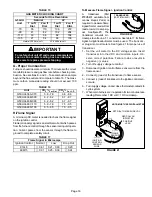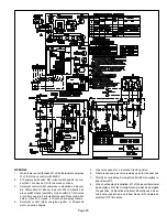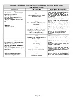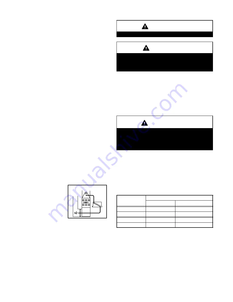
STATIC PRESSURE TEST
FIGURE 22
Page 20
V−TYPICAL OPERATING CHARACTERISTICS
A−Blower Operation and Adjustment
1 − Blower operation is dependent on thermostat control
system.
2 − Generally, blower operation is set at thermostat sub-
base fan switch. With fan switch in ON position, blower
operates continuously. With fan switch in AUTO position,
blower cycles with demand or runs continuously while
heating or cooling circuit cycles.
3 − Depending on the type of indoor thermostat, blower
and entire unit will be off when the system switch is in
OFF position.
B−Temperature Rise
Temperature rise for G50UHi units depends on unit input,
blower speed, blower horsepower and static pressure as
marked on the unit rating plate. The blower speed must be
set for unit operation within the range of TEMP. RISE
°
F"
listed on the unit rating plate.
To Measure Temperature Rise:
1 − Place plenum thermometers in the supply and return air
plenums. Locate supply air thermometer in the first hori-
zontal run of the plenum where it will not pick up radiant
heat from the heat exchanger.
2 − Set thermostat to highest setting.
3 − After plenum thermometers have reached their high-
est and steadiest readings, subtract the two readings.
The difference should be in the range listed on the unit
rating plate. If the temperature is too low, decrease
blower speed. If temperature is too high, first check the
firing rate. Provided the firing rate is acceptable, in-
crease blower speed to reduce temperature.
C−External Static Pressure
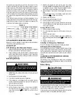
1 − Tap locations shown in figure 22 .
2 − Punch a 1/4" diameter hole
in supply and return air ple-
nums. Insert manometer
hose flush with inside edge
of hole or insulation. Seal
around the hose with perma-
gum. Connect the zero end
of the manometer to the dis-
charge (supply) side of the system. On ducted sys-
tems, connect the other end of manometer to the return
duct as above. For systems with non−ducted returns,
leave the other end of the manometer open to the at-
mosphere.
3 − With only the blower motor running and the evaporator
coil dry, observe the manometer reading. Adjust blow-
er motor speed to deliver the air desired according to
the job requirements.
4 − External static pressure drop must not be more than
0.5" W.C.
5 − Seal around the hole when the check is complete.
VI−MAINTENANCE
WARNING
Disconnect power before servicing unit.
CAUTION
Label all wires prior to disconnection when servicing
controls. Wiring errors can cause improper and dan-
gerous operation. Verify proper operation after ser-
vicing.
At the beginning of each heating season, a qualified techni-
cian should check the system as follows:
Blower
Check the blower wheel for debris and clean if necessary.
The blower motors are prelubricated for extended bearing
life. No further lubrication is needed.
WARNING
The blower access panel must be securely in place
when the blower and burners are operating. Gas
fumes, which could contain carbon monoxide, can
be drawn into living space resulting in personal inju-
ry or death.
Filters
All G50UHi filters are installed external to the unit. Filters
should be inspected monthly. Clean or replace the filters
when necessary to ensure that the furnace operates prop-
erly. Replacement filters must be rated for high velocity air-
flow. Table 18 lists recommended filter sizes.
TABLE 18
Furnace
Filter Size
Furnace
Cabinet Size
Side Return
Bottom Return
14−1/2"
16 X 25 X 1 (1)
14 X 25 X 1 (1)
17−1/2"
16 X 25 X 1 (1)
16 X 25 X 1 (1)
21"
16 X 25 X 1 (1)
20 X 25 X 1 (1)
24−1/2"
16 X 25 X 1 (2)
24 X 25 X 1 (1)
Flue And Chimney
Check the flue pipe, chimney and all connections for tight-
ness and to make sure there is no blockage.
Electrical
1 − Check all wiring for loose connections.
2 − Check for the correct voltage at the furnace (furnace
operating).
3 − Check amp−draw on the blower motor.
Motor Nameplate__________Actual__________
Summary of Contents for G50UHi Series
Page 6: ...Page 6 FIGURE 1...

