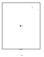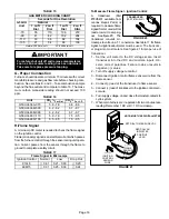
FIGURE 20
TRANSDUCER
(PART #78H5401)
Page 19
TABLE 15
GAS METER CLOCKING CHART
Seconds for One Revolution
G50UH
Natural
LP
G50UH
Unit
1 cu ft
Dial
2 cu ft
Dial
1 cu ft
Dial
2 cu ft
DIAL
−70
55
110
136
272
−90
41
82
102
204
−110
33
66
82
164
−135
27
54
68
136
Natural−1000 btu/cu ft LP−2500 btu/cu ft
IMPORTANT
For safety, shut unit off and remove manometer as
soon as an accurate reading has been obtained.
Take care to replace pressure tap plug.
G− Proper Combustion
Furnace should operate minimum 15 minutes with correct
manifold pressure and gas flow rate before checking com-
bustion. See sections E− and F−. Take combustion sample
beyond the flue outlet and compare to table 16. The maxi-
mum carbon monoxide reading should not exceed 100
ppm.
TABLE 16
Unit
CO
2
%
For Nat
CO
2
%
For L.P.
G50UHi−36A−070
5.8 − 7.8
6.8 − 8.8
G50UHi−36B−090
6.2 − 8.2
6.7 − 8.7
G50UHi−48B−090
6.2 − 8.2
6.7 − 8.7
G50UHi−60C−110
5.9 − 7.9
7.5 − 9.5
G50UHi−60D−135
6.5 − 8.5
7.5 − 9.5
H−Flame Signal
A microamp DC meter is needed to check the flame signal
on the ignition control.
Flame (microamp) signal is an electrical current which passes
from the furnace control through the sensor during unit opera-
tion. Current passes from the sensor through the flame to
ground to complete a safety circuit.
TABLE 17
Flame Signal in Microamps
Ignition Control
Normal
Low
Drop Out
97L48
0.61
0.21 − 0.60
0.20
69M15
0.31
0.25 − 0.30
0.24
To Measure Flame Signal − Ignition Control:
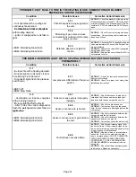
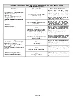
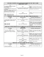
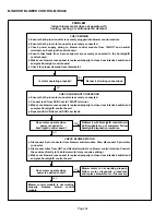
A transducer (Part
#78H5401 available from
Lennox Repair Parts) is
required to measure flame
signal if meter used will not
read a low micro amp sig-
nal. Seefigure20. The
transducer converts mi-
croamps to volts on a 1:1 conversion. See table 17 for flame
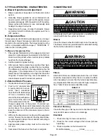
signal. A digital readout meter must be used. The transduc-
er plugs into most meters. See figure 21 for proper use of
transducer.
1 − Set the volt meter to the DC voltage scale. Insert
transducer into the VDC and common inputs. Ob-
serve correct polarities. Failure to do so results in
negative (−) values.
2 − Turn off supply voltage to control.
3 − Disconnect ignition control flame sensor wire from the
flame sensor.
4 − Connect (−) lead of the transducer to flame sensor.
5 − Connect (+) lead of transducer to the ignition control sen-
sor wire.
6 − Turn supply voltage on and close thermostat contacts to
cycle system.
7 − When main burners are in operation for two minutes, take
reading. Remember 1 DC volt = 1 DC microamp.
SET DIAL TO MEASURE VDC
(+)
(−) TO
FLAME
SENSOR
NOTE−MUST USE DIGITAL METER
RED COLLAR
INDICATES
POSITIVE
LEAD
(+) TO
IGNITION
CONTROL
SENSOR
WIRE
FIGURE 21
(−)
Summary of Contents for G50UHi Series
Page 6: ...Page 6 FIGURE 1...

