Page 8
C-Installation on Cooling Cabinet
1- Refer to reverse-flow coil installation instructions for corĆ
rectly sized opening in floor and installation of cabinet.
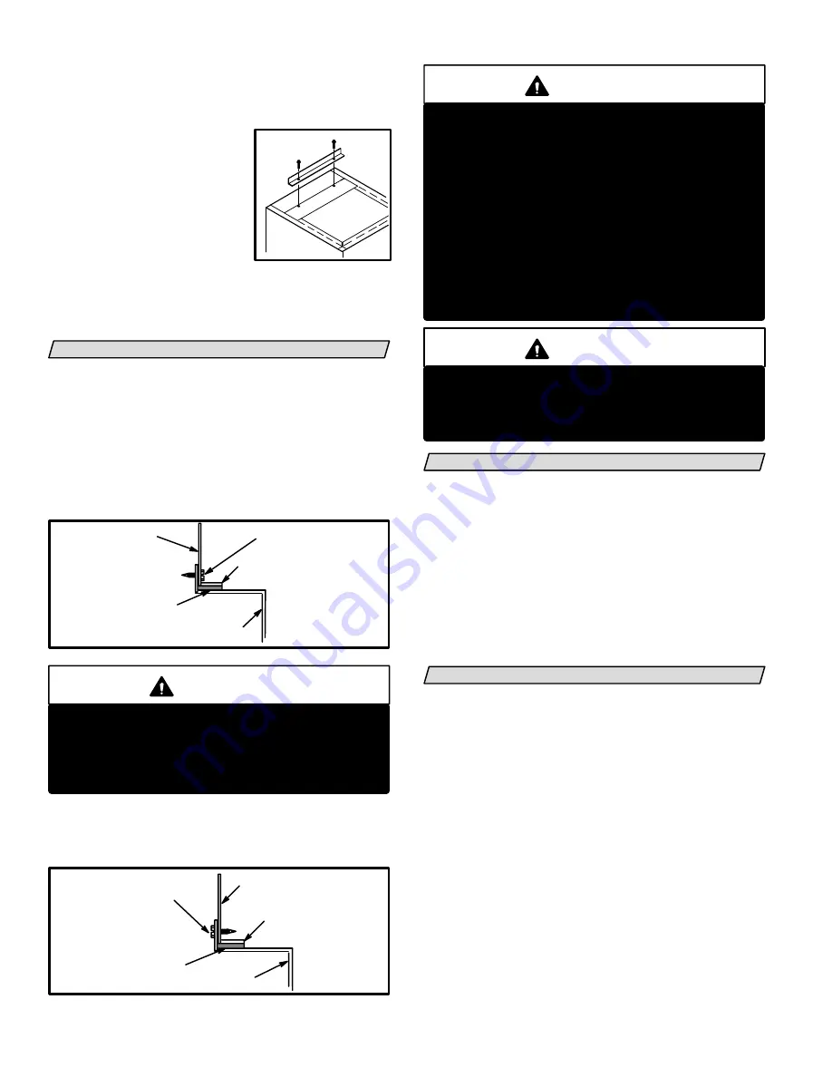
2- Use duckbill pliers to bend
unit flanges out from openĆ
ing. Install provided base
bottom angle (shipped in
vestibule panel) to outside of
base into provided holes.
See illustration at right. SeĆ
cure with screws provided.
3- With cooling cabinet in place, install furnace so
flanges drop inside cabinet opening. Secure furnace
to cabinet.
4- Seal cabinet and check for air leakage.
RETURN AIR OPENING GUIDELINES
Take the following steps when installing return air
plenum:
1- Bottom edge of plenum should be flanged with a
hemmed edge. See figure 8.
2- Fiberglass sealing strips should be used between pleĆ
num and the unit cabinet to ensure a tight seal.
3- In all cases, the plenum should be secured to the top
flanges of the furnace using sheet metal screws. See
figure 8.
FIGURE 8
SECURE
HEMMED EDGE
PLENUM
CABINET SIDE PANEL
FIBERGLASS
SEALING STRIP
WARNING
Do not put sheet metal screws into top of furnace.
Sheet metal screws must be installed into flange of
furnace. Note warning stickers on unit. MisplaceĆ
ment of screws may prevent normal maintenance
of filters.
4- In closet installations, it may be necessary to install
sheet metal screws from the inside. If this is the case,
make plenum with a removable front to install screws
as shown in figure 9.
FIGURE 9
SECURE FROM
INSIDE
HEMMED EDGE
FIBERGLASS
SEALING STRIP
CABINET SIDE PANEL
PLENUM
WARNING
Improper installation of unit can result in personal
injury or death. Combustion and flue products must
never be allowed to enter the return air system or air
in the living space. Use sheet metal screws and joint
tape to seal return air system to furnace.
The furnace should be sealed airtight to the return
air plenum. A door must never be used as a portion
of the return air duct system. Allow absolutely no
sagging, cracks, gaps, etc.
For no reason should return and supply air duct
systems ever be connected to or from other heatĆ
ing devices such as a fireplace or stove, etc. Fire,
explosion, carbon monoxide poisoning, personal
injury and/or property damage could result.
WARNING
Blower door must be securely in place when blowĆ
er and burners are operating. Gas fumes, which
could contain carbon monoxide, can be drawn into
living space resulting in personal injury or death.
DUCT SYSTEM
Size and install the supply and return air duct system usĆ
ing industry-approved standards that result in a quiet
and low-static system with uniform air distribution.
Installation of units not equipped with a cooling coil reĆ
quire a removable access panel in the supply air duct.
The access panel should be large enough to permit inĆ
spection of heat exchanger for leaks after installation.
Lennox recommends using the SENSIT
TM
HT kit for
heat exchanger inspections. The access panel must not
allow leaks in the supply air duct system.
VENTING
G20R furnaces must be vented in compliance with all
local codes, the current GAMA/A.G.A. venting tables
manual (502,567M) in the U.S.A. and the current stanĆ
dards of CAN/CGA-B149.1 and -B149.2 in Canada and
these instructions.
The G20R series units have been classified as Category
I type furnaces when vertically vented in accordance
with the latest edition of ANSI Z21.47 Central Furnace
Standard in the U.S.A. and the current standard of
CAN/CGA-B149.1 and B149.2 of the National Gas and
Propane Installation Code in Canada.
General Venting Recommendations & Requirements
For Using Masonry Chimney
Any masonry chimney used for venting a G20R gas furĆ
nace must be lined, and must be sized and installed per
all applicable local building codes or, in the absence of
local codes, the current National Fuel Gas Code (ANSI-
Z223.1) in the U.S.A. and the current standards of CAN/
INSTALLING
BASE ANGLE


