background image

Page 7

When ducts are used, they shall be of the same cross-

sectional area as the free area of the openings to which

they connect. The minimum dimension of rectangular

air ducts shall be no less than 3 inches. In calculating

free  area,  the  blocking  effect  of  louvers,  grilles,  or

screens must be considered. If the design and free area

of protective covering is not known for calculating the

size opening required, it may be assumed that wood

louvers will have 20 to 25 percent free area and metal

louvers and grilles will have 60 to 75 percent free area.

Louvers and grilles must be fixed in the open position

or  interlocked  with  the  equipment  so  that  they  are

opened automatically during equipment operation.

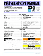
EQUIPMENT IN CONFINED SPACE

ALL AIR FROM OUTSIDE

OUTLET AIR

INLET AIR

WATER

HEATER

CHIMNEY

OR GAS

VENT

FIGURE 6

NOTE-Each air duct opening shall have a free area of at least one

square inch per 2,000 Btu per hour of the total input rating of all equipĆ

ment in the enclosure. If the equipment room is located against an outĆ

side wall and the air openings communicate directly with the outdoors,

each opening shall have a free area of at least one square inch per

4,000 Btu per hour of the total input rating of all other equipment in the

enclosure.

G20R

FURNACE

INSTALLATION–Setting Equipment

The G20R series units can be installed in three different
ways:  on  non-combustible  flooring,  on  combustible
floor using an additive base, or on a reverse-flow coolĆ
ing cabinet. Do not drag unit across floor.

A-Installation on Non-Combustible Flooring

 1- Cut  floor  opening  keeping  in  mind  the  clearances

listed on the unit rating plate. Also, keep in mind gas

supply and electrical supply, vent connections and

sufficient  installation  and  service  clearances.  See

table 2 for correct floor opening size.

TABLE 2

NONCOMBUSTIBLE FLOOR

UNIT

Front to Rear

Side to Side

in

mm

in

mm

Q2/3-50, Q3-75

Q4-75, Q3/4-100

Q5-100, Q3-125, Q4/5-125

Q4/5-150

20-1/2

20-1/2

20-1/2
20-1/2

520

520

520
520

12-1/4

17-1/4

22-1/4
27-1/4

311

438

565
692

NOTE-Floor opening dimensions listed are 1/4" (6mm) larger

than unit openings.

 2- Flange warm air plenum and lower into opening.

 3- Use  duckbill  pliers  to  bend

unit  flanges  out  from  openĆ

ing.  Install  provided  base

bottom  angle  (shipped  in

vestibule panel) to outside of

base  into  provided  holes.

See  illustration  at  right.  SeĆ

cure with screws provided.

 4- Set unit over plenum.
 5- Check to see that an adequate seal is made.

B-Installation on Combustible Flooring

 1- When unit is installed on a combustible floor, an addiĆ

tive base (ordered separately) must be installed beĆ

tween the furnace and the floor. See table 3 for openĆ

ing size to cut in the floor.

TABLE 3

ADDITIVE BASE  FLOOR OPENING

UNIT

Front to Rear

Side to Side

in

mm

in

mm

Q2/3-50, Q3-75

Q4-75, Q3/4-100

Q5-100, Q3-125, Q4/5-125

Q4/5-150

22-7/8

581
581
581
581

14-5/8
19-5/8
24-5/8
29-5/8

371
498
625
752

NOTE-Floor opening dimensions listed are 1/4" (6mm) larger

than unit openings.

22-7/8
22-7/8
22-7/8

 2- After opening is cut, set the additive base into opening.
 3- Check fiberglass strips on additive base to make sure

they are properly glued and positioned.

 4- Lower supply air plenum into additive base until pleĆ

num flanges seal against fiberglass strips.

 5- Use  duckbill  pliers  to  bend

unit  flanges  out  from  openĆ

ing.  Install  provided  base

bottom  angle  (shipped  in

vestibule panel) to outside of

base  into  provided  holes.

See  illustration  at  right.  SeĆ

cure with screws provided.

 6- Set unit on additive base so unit flanges drop into pleĆ

num. Refer to figure 7.

NOTE-Be  careful  not  to  damage  fiberglass  strips.

Check for tight seal.

FIGURE 7

G20R UNIT

SUPPLY AIR

PLENUM

ADDITIVE

BASE

PROPERLY

SIZED

FLOOR

OPENING

1. Cut correct size floor opening
2. Set additive base into opening.
3. Set supply air plenum into

additive base.

4. Set unit.

INSTALLING

BASE ANGLE

INSTALLING

BASE ANGLE

Summary of Contents for G20R series

Page 1: ...BLESHOOTING 20 RETAIN THESE INSTRUCTIONS FOR FUTURE REFERENCE WHAT TO DO IF YOU SMELL GAS If the information in this manual is not followed exactly a fire or explosion may result causing property damage personal injury or loss of life WARNING Do not store or use gasoline or other flammable vapors and liquids in the vicinity of this or any other appliance Installation and service must be performed ...

Page 2: ...ecĆ tion or to help in alignment with cooling coil ă Dimensions before flanges are bent as shipped Dimensions after flanges are bent Dimension after flange furnished is field installed on unit M d l N A B C C D D E Model No inch mm inch mm inch mm inch mm inch mm inch mm inch mm G20RQ2 3 X EĆ50 G20RQ3 X EĆ75 16Ć1 4 413 14Ć1 8 359 10Ć3 4 273 12 305 1Ć1 2 38 2Ć1 8 54 3Ć1 8 79 G20RQ4 X EĆ75 21Ć1 4 54...

Page 3: ...Y LIMIT CONTROL CABINET ROLL OUT SWITCH GAS VALVE PILOT ELECTRODE ASSEMBLY FLUE TRANSITION LOWER ACCESS PANEL FILTER ACCESS DOOR DOOR INTERLOCK SWITCH BCC CONTROL REMOVABLE STRIP BLOCKED VENT SHUT OFF SWITCH DAMPER MOTOR GEAR PATCH PLATE PATCH PLATE SPRING DAMPER SWITCH DAMPER SWITCH COVER ROLL OUT SWITCH DAMPER BURNER BOX DAMPER BOX PARTS ARRANGEMENT G20R Units Shown REMOVABLE BURNER BOX TOP FIGU...

Page 4: ...stible material other than wood flooring For installation in a residential garage unit must be installed so that burner s and ignition source are loĆ cated no less than 18 in 457 mm above floor Furnace must be located or protected to avoid physical damage by vehicles Unit must be adjusted to obtain a temperature rise within the range specified on appliance rating plate The draft hood shall be inst...

Page 5: ...xhaust vents and gas pipĆ ing A portion of this information has been reprinted with permission from the National Fuel Gas Code ANSI Z223 1 This reprinted material is not the complete and official position of the ANSI on the referenced subject which is represented only by the standard in its entirety In Canada refer to the standard CAN CGA B149 1 and B149 2 installation codes Combustion Air Require...

Page 6: ...ATER HEATER OPENINGS To Adjacent Room FIGURE 3 NOTE Each opening shall have a free area of at least one square inch per 1 000 Btu per hour of the total input rating of all equipment in the enclosure but not less than 100 square inches G20R FURNACE CHIMĆ NEY OR GAS VENT Air from Outside If air from outside is brought in for combustion and venĆ tilation the confined space must have two permanent ope...

Page 7: ... FLOOR UNIT Front to Rear Side to Side in mm in mm Q2 3 50 Q3 75 Q4 75 Q3 4 100 Q5 100 Q3 125 Q4 5 125 Q4 5 150 20 1 2 20 1 2 20 1 2 20 1 2 520 520 520 520 12 1 4 17 1 4 22 1 4 27 1 4 311 438 565 692 NOTE Floor opening dimensions listed are 1 4 6mm larger than unit openings 2 Flange warm air plenum and lower into opening 3 Use duckbill pliers to bend unit flanges out from openĆ ing Install provide...

Page 8: ...turn air plenum A door must never be used as a portion of the return air duct system Allow absolutely no sagging cracks gaps etc For no reason should return and supply air duct systems ever be connected to or from other heatĆ ing devices such as a fireplace or stove etc Fire explosion carbon monoxide poisoning personal injury and or property damage could result WARNING Blower door must be securely...

Page 9: ...lothes dryers and any appliances not connected to the common venting system Turn on any exhaust fans such as range hoods and bathĆ room exhausts so they will operate at maximum speed Do not operate a summer exhaust fan Close fireplace dampers 4 Follow the lighting instructions Place the appliance being inspected in operation Adjust thermostat so appliance will operate continuously 5 Test for spill...

Page 10: ... properly labeled by the inĆ staller FIGURE 12 GROUND JOINT UNION AUTOMATIC GAS VALVE with manual shut off valve FIELD PROVIDED AND INSTALLED GROUND JOINT UNION LEFT SIDE PIPING STANDARD RIGHT SIDE PIPING ALTERNATE AUTOMATIC GAS VALVE with manual shut off valve DRIP LEG DRIP LEG MANUAL MAIN SHUT OFF VALVE With 1 8 NPT Plugged Tap Shown MANUAL MAIN SHUT OFF VALVE With 1 8 NPT Plugged Tap Shown TABL...

Page 11: ...0 110 43 3700 104 77 3450 97 69 3250 92 03 4 101 6 4 026 102 260 23000 651 27 15800 447 39 12800 362 44 10900 308 64 9700 274 67 8800 249 18 8100 229 36 7500 212 37 7200 203 88 6700 189 72 NOTE Capacity given in cubic feet of gas per hour kilo liters of gas per hour and based on 0 60 specific gravity gas ...

Page 12: ...plugs are provided on both sides of cabinet to facilitate wiring 3 Install room thermostat according to instructions proĆ vided with thermostat 4 Install a separate fused disconnect switch near the unit so power can be turned off for servicing 5 Route thermostat wire as shown in figure 14 Keep wire away from draft hood and flue pipe Do not route wire across draft hood 6 Complete wiring connections...

Page 13: ...NAL COOLING SPEED TAP TERMINAL DUMMY TERMINALS CONTINUOUS FAN TERMINAL THERMOSTAT JUMPER Electronic or Mechanical FIGURE 16 Y R W G G W Y T R BCC CONTROL THERMOSTAT IGNITION CONTROL GAS VALVE DAMPER DOOR SWITCH FLAME ROLLOUT SWITCH PRIMARY LIMIT BLOCKED VENT SHUTOFF SWITCH BLACK WHITE TO COMPRESSOR CONTACTOR FIELD INSTALLED LOW VOLTAGE FIELD INSTALLED LINE VOLTAGE TYPICAL G20R FIELD WIRING DIAGRAM...

Page 14: ...Page 14 FIGURE 17 TYPICAL G20R WIRING DIAGRAM ...

Page 15: ...l automatically light The pilot goes out when there is no demand for heat WARNING If you do not follow these instructions exactly a fire or explosion may result causing property damage personal injury or loss of life Gas Valve Operation Figures 19 20 1 STOP Read the safety information at the beginning of this section 2 Set thermostat to lowest setting See figure 18 3 Turn off all electrical power ...

Page 16: ... Gas Pressure 1 Check gas line pressure with unit firing at maximum rate A minimum of 4 5 w c 1 12kPa for natural gas or 10 5 w c 2 61kPa for LP propane gas should be maintained 2 After line pressure has been checked and adjusted check manifold pressure Correct manifold presĆ sure for LP propane gas is 9 5 w c 2 36kPa No adĆ justment is needed in high altitude applications A natural gas to LP prop...

Page 17: ...ning 5 Grasp blower motor harness connector located on back on motor Depress lock tab and pull connector from motor 6 Pull harness connector and wires through blower acĆ cess panel opening 7 Select desired taps for heating and cooling White common Red heating Black cooling 8 Depress harness connector tab to release wire termiĆ nal Select connector location for new speed refer to unit wiring diagra...

Page 18: ...wing procedure and figure 27 to clean filter TABLE 5 MODEL NO FILTER SIZE Q2 3 50 Q3 75 Q4 75 Q3 4 100 Q5 100 Q3 125 Q4 5 125 20 X 10 X 1 20 X 12 X 1 20 X 14 X 1 Q4 5 150 20 X 16 X 1 FIGURE 27 BLOWER RIGHT FILTER LEFT FILTER LEFT SUPPORT ANGLE RIGHT FILTER SUPPORT ANGLE ON THREE SIDES 150 UNITS MAKE SURE FILTER IS PLACED INTO THIS CHANNEL 150 UNITS ROTATE FILTER TO REMOVE TAB 1 Turn off electric p...

Page 19: ...h Continue with items 13 through 15 below and reinstall flame rods and springs 13 Clean top of burner ports with a wire brush See figĆ ure 29 14 Clean burner ports by inserting a cleaning tool made from a piece of sheet metal cut to fit the burner ports and work in and out of each port See figure 30 15 Clean inside of each burner with a bottle cleaning brush See figure 31 CLEANING TOP FIGURE 29 CL...

Page 20: ... burner with pilot mount Flue baffles Pilot electrode assembly Primary limit control Flame roll out switch Blocked vent shut off switch Damper motor Damper switch Couplings Damper spring Grommets G20RE START UP AND PERFORMANCE CHECK LIST Filter Clean Secure Supply Voltage Electrical Connections Tight START UP AND PERFORMANCE CHECK LIST Job Name Job Location Installer Unit Model No Furnace Btu Inpu...

Page 21: ... REPLACE BCC NO IS 120VAC ACROSS N CAB CHECK DAMPER MOTOR WIRING AND DAMPER MOTOR YES YES IS UNIT LIT NO CHECK 1 DAMPER MOTOR 2 IGNITION CONTROL 3 GAS VALVE 4 IGNITOR 5 LIMIT SWITCHES 6 PROVE SWITCH YES IS BLOWER RUNNING ON LOW SPEED 45 SEC AFTER FURNACE LIGHTS NO IS 120VAC ACROSS N H YES IS 24VAC ACROSS C V REPLACE BCC NO NO CHECK WIRING YES IS 120VAC ACROSS N ACC YES REMOVE R W JUMPER AFTER THE ...

Reviews: