background image


Retracting/extending the side sections


52 

9 RETRACTING/EXTENDING THE SIDE SECTIONS 

DANGER


Risk of accident due to incorrect retraction of the side sections

Incorrect retraction of the side sections will result in accidents if the-
re are people in the slewing and folding area of the side section or if 
there are high-voltage lines in the slewing and folding area of the 
side sections. See section entitled "Hazardous areas". 

 Before retracting, check that there is nobody within the slewing 

and folding area of the side sections. 

 Never retract the side sections if there are high-voltage lines in 

the slewing and folding area of the side sections. 

  Do not retract the side sections until the device has been fully rai-

sed. 


DANGER 


Damage to the implement 

Driving with unlocked tractor control units may cause the side sec-
tions to extend unintentionally during transportation if the side sec-
tions are not interlocked by the hydraulic transport lock.  

As a result, other road users may be injured or killed while the im-
plement is being transported.  

As a result, people in the immediate vicinity may be injured or killed.

  Always lock the control unit of the tractor before transportation. 

 Ensure that the hydraulic transport lock is always locked in the 

implement's transport position. 


Summary of Contents for Kristall 9 K

Page 1: ...ltivator Kristall 9 K KU EN Item no 175_4840 2 04 11 LEMKEN GmbH Co KG Weseler Stra e 5 D 46519 Alpen PO Box 11 60 D 46515 Alpen Telephone 0 28 02 81 0 Fax 0 28 02 81 220 E mail lemken lemken com Inte...

Page 2: ......

Page 3: ...ting instructions contain important information about how to operate the device safely properly and efficiently Following the instructions will help to pre vent hazards faults and down times and will...

Page 4: ...arts state the type designation and serial number of the device This information can be found on the rating plate Enter this data in the fields below so that it is always to hand Type designation Seri...

Page 5: ...ded use 12 3 3 Safety equipment on the device 13 3 4 Safety and warning signs 14 3 4 1 General information 14 3 4 2 Meaning of warning signs 14 3 4 3 Position of safety and warning signs 16 3 5 Specia...

Page 6: ...the device 32 5 Design and function 33 5 1 Overview 33 5 2 Function 34 5 2 1 Three point tower 34 5 2 2 Frame 34 5 2 3 Tines 34 5 2 4 Working depth adjustment of the tines 34 5 2 5 Automatic overload...

Page 7: ...n 49 8 2 Protective devices 49 8 3 Transport dimensions 51 9 Retracting extending the side sections 52 9 1 Retracting 53 9 2 Extending 54 10 Adjustments 56 10 1 Working depth of tines 57 10 1 1 Genera...

Page 8: ...2 Attaching the share base 82 12 Switching off the device 83 12 1 Shutting down the device in an emergency 83 12 2 Disposal 83 13 Maintenance and repairs 84 13 1 Special safety instructions 84 13 1 1...

Page 9: ...ng torques 92 13 5 1 Wheel nuts 92 13 5 2 Other screw connections 92 13 6 Checking connections to the tractor 93 13 7 Air pressure of tyres 94 13 8 Scrapers 94 13 8 1 Scrapers on rubber ring roller 94...

Page 10: ...ance with the operating instructions and the enclosed safety instruc tions unauthorised changes to the device inadequate monitoring of parts which are subject to wear maintenance work that has not bee...

Page 11: ...e im plement They contain texts and drawings which must not be reproduced divulged or communicated in any other way in whole or in part without the express permis sion of the manufacturer Infringement...

Page 12: ...arly im portant information DANGER Denotes an imminent hazard with high risk which will result in death or severe physical injury if not avoided WARNING Denotes a possible hazard with medium risk whic...

Page 13: ...r important information for operation and efficient utilisation 2 3 Environmental protection Indication of special recycling and environmental protection measures 2 4 Indication of passages The follow...

Page 14: ...vice may result in a risk to life and limb of the user or third parties or cause damage to the device and other ma terial property The device may be operated in a technically perfect condition only in...

Page 15: ...equipment on the device To protect the user and the device the device features special safety equipment Always keep all safety equipment in working order Warning signs with light Hydraulic fold out lo...

Page 16: ...s Damaged lost or illegible warning signs must be replaced immediately The indicated article numbers are used as order numbers 3 4 2 Meaning of warning signs Familiarise yourself with the meaning of t...

Page 17: ...not remain in the operating and swivel area of the device ATTENTION Danger of crushing CAUTION Keep out of the folding area of the de vice CAUTION The front axle of the tractor must always be loaded...

Page 18: ...Safety measures and precautions 16 3 4 3 Position of safety and warning signs...

Page 19: ...jury The operator must personally monitor all work on and with the device The operator instructs his personnel in occupational safety ac cording to the currently valid occupational safety guidelines W...

Page 20: ...ed hydraulic equipment As a result functions may run in the opposite direction or may be inverted Before actuating the hydraulics check that the hydraulic con nections of the device are connected to t...

Page 21: ...azardous area The hazardous area of the device moves during operation of the device During operation of the device there must be nobody in front of the actual hazardous area as the hazardous area move...

Page 22: ...Safety measures and precautions 20 3 6 2 Hazardous area when folding the device in and out...

Page 23: ...machine parts on moving machine parts caused by stored mechanical energy in elastic parts such as springs on an inadequately stable device on the general shape or mounting location of components 3 7...

Page 24: ...ules which must be observed during operation of the device are listed below Observe the currently valid national highway code Observe the currently valid national laws and regulations for occupational...

Page 25: ...rve the permitted axle loads gross weights and transportation dimensions see also section entitled Axle loads Observe the permitted power limit of the tractor WARNING Risk of accidents due to inadequa...

Page 26: ...ross weight of tractor permissible axle loads of tractor the tractor s tyre load carrying capacities The tractor s front axle must always be loaded with at least 20 of the tractor s curb weight The fo...

Page 27: ...eight Abbreviation Data GH Gross weight kg for rear mounting implement or rear weight _______ kg GV Gross weight kg for front mounting implement or front weight _______ kg d Distance m between centre...

Page 28: ...t the rear of the tractor into the table Calculation of actual gross weight Gtat Enter the value for the calculated actual gross weight and the permissible gross weight as given in the tractor s opera...

Page 29: ...e value for two tyres for the permissible tyre load carrying ca pacity see e g tyre manufacturer s documentation into the table Table Actual value ac cording to calculation Permissible value according...

Page 30: ...uate themselves in any position Before starting up and operating the device check the immediate vicinity around the device There must be nobody here Ensure that visibility is ade quate Observe permitt...

Page 31: ...ilable at the installa tion location of the device and are kept for the entire service life of the device If the device is sold or the operating company changes pass on the operating instructions with...

Page 32: ...o the position which prevents the device from being uninitentionally raised or lowered When actuating the external control for the three point attachment do not walk between the tractor and device It...

Page 33: ...n the device may be carried out by trained and instructed personnel only Personnel must not be on drugs intoxicated or taking medication Servicing and maintenance work may be carried out by trained te...

Page 34: ...vered ensure that it corresponds with the order package Also check the type and completeness of any supplied accessories When the device is handed over your dealer will explain how it works As soon as...

Page 35: ...wer 2 Frame 3 Tines 4 Working depth adjustment for tines 5 Automatic overload safety device for tines 6 Hollow discs serrated 7 Edge discs 8 Roller double roller DRR 400 400 9 Hydraulic transport lock...

Page 36: ...e elements Overload safety device elements cannot be used on a frame with tine pockets 5 2 3 Tines Either tines with a permanently integrated share foot or tines with quick change system can be used a...

Page 37: ...vailable with an automatic overload safety device 5 2 8 Rollers The rollers ensure reconsolidation and additional crumbling of the soil During op eration on the land they bear the weight of the implem...

Page 38: ...Design and function 36 5 2 12 Lighting system The lighting system contributes significantly to increasing the safety of the imple ment in road traffic...

Page 39: ...that the lower links are always free to move sideways during working 6 4 Required power sources CAUTION Damage to electrical components The tolerance range for the power supply is between 10 V and 15...

Page 40: ...onnections are colour coded and the hydraulic connections themselves are alphanumerically coded For operation of the individual hydraulic devices listed below the tractor must be equipped with the fol...

Page 41: ...er road users may be injured or killed while the im plement is being transported Only use drawbars and top link pins that comply with a category corresponding to the tractor s output in accordance wit...

Page 42: ...is available in the following table Working width 400 cm 500 cm 600 cm Drawbar Category 3 Category 3 Category 3 Drawbar Category 3N Category 3N Category 3N Drawbar Category 4N Category 4N Category 4N...

Page 43: ...operating instructions of the tractor manufacturer 6 7 2 Work assignment For use on the land switch the hydraulic system of the tractor to float position or mixed control See operating instructions o...

Page 44: ...the hydraulic hoses to the tractor hydraulics check that the hydraulics are depressurised on the tractor and device Always ensure that the hydraulic hoses are connected as stipu lated To prevent oper...

Page 45: ...red the pintle of the drawbar may slip out As a result the implement may fall down and injure or kill people in the immediate vicinity As a result other road users may be injured or killed while the i...

Page 46: ...tractor as specified in the table in the Required hydraulic equipment section Connect the electrical cables to the trac tor as specified in the table in the Re quired power sources section Now drive u...

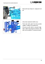
Page 47: ...7 using the linch pin Lift out the implement all the way Fold in the side parts See also section entitled Folding in the side parts If the drive to the field is via public high ways attach the protec...

Page 48: ...remove it Remove the upper control link 5 from the three point tower 6 and position it in the designated holder on the tractor Release the safety equipment 4 and remove the lower links 2 from the pint...

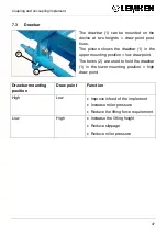
Page 49: ...the upper mounting position low draw point The bores 2 are used to hold the drawbar 1 in the lower mounting position high draw point Drawbar mounting position Draw point Function High Low Improve inf...

Page 50: ...ntrol link pin must always be secured Nobody may be in the immediate vicinity of the implement when it is lifted out The top link 1 can be mounted in several positions on the three point tower 2 A tot...

Page 51: ...sk of injury Other road users could be injured by the tines Always attach the protective devices before driving on public highways Before transporting on public highways cover the tines 1 of the side...

Page 52: ...ng straps 4 Plug the connectors for the front bound ary lights power supply into the corre sponding sockets at the front on the im plement When working the transport protection can be positioned on th...

Page 53: ...ection entitled Retracting the side sections In conjunction with a 6 m working width the device may have to be lowered slightly after the device has been lifted out all the way and retracted to ensure...

Page 54: ...act the side sections if there are high voltage lines in the slewing and folding area of the side sections Do not retract the side sections until the device has been fully rai sed DANGER Damage to the...

Page 55: ...der 2 up to the end position In doing so the hydraulic transport lock automatically engages Check whether the hooks 4 of the hydraulic transport lock 3 are properly locked the hydraulic cylinder 5 is...

Page 56: ...es in the slewing and folding area of the side sections See section entitled Hazardous areas Before extending the side sections check that there is nobody within the hazardous area of the side section...

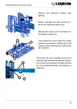
Page 57: ...l unit of the tractor for the folding cylinders 2 Then switch the control unit to the retract position 1st pressure position and then quickly to the extend position 2nd pres sure position The hooks 4...

Page 58: ...our hands feet and body on heavy and occasionally compressed and or sharp edged parts Always park implement on the ground Adjustment work may be carried out by appropriately instructed personnel only...

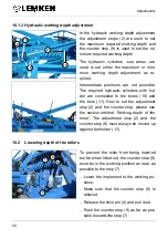
Page 59: ...orter the distance between the stop 7 and end 8 of the strut in the working position the larger the working depth The longer the distance between the stop 7 and end 8 of the strut in the working posit...

Page 60: ...are connected to the bores 10 and the bore 11 How to set the adjustment stop 2 and the counter stop please see the section entitled Working depth of the tines The adjustment stop 2 and the counter st...

Page 61: ...Adjustments 59 Use spacer plates to compensate for any gap 12 between the counter stop 9 and stop 7 Fix the counter stop 9 with the linch pin 4 and secure the linch pin 4...

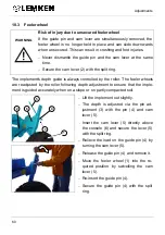
Page 62: ...er The feeler wheels are readjusted by the roller following depth adjustment to ensure that the imple ment is guided accurately when on a slope or on partly compacted soil Lift the implement out sligh...

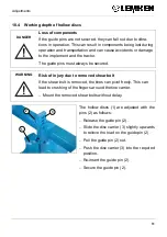
Page 63: ...lways be secured WARNING Risk of injury due to removed shear bolt If the shear bolt is removed the tines can pivot freely This can lead to crushing of the fingers around the tine carrier Mount the rem...

Page 64: ...ays be secured WARNING Risk of injury due to removed shear bolt If the shear bolt is removed the tine can pivot freely This can lead to crushing of the fingers around the tine carrier Mount the remove...

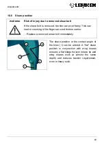
Page 65: ...shing of the fingers around the tine carrier Replace a removed shear bolt immediately The share position or the contact angle of the tines 1 can be altered A flat share position in conjunction with wi...

Page 66: ...hare position is altered by inserting the shear bolt 2 in a different position Flat share position Insert the shear bolt through the hole 4 of the tine carrier 3 and the hole 5 of the tine 1 Steep sha...

Page 67: ...ew centime tres Loosen and remove nut from the shear bolt 2 Press out the shear bolt using a suitable tool Tilt the tine into the desired position Insert the shear bolt as required into the hole 4 or...

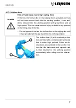
Page 68: ...all the way back into the working position DANGER Risk of accidents due to moving tines When an obstruction is encountered the tine tilts very quickly up wards by spring force This can cause injury to...

Page 69: ...use serious injury or death to any persons in the tilting area of the tine Do not approach the tine the hollow disc or the edging disc until it has swivelled all the way back into the working position...

Page 70: ...ult people who are in the swivel area of the tine may be seriously injured or even killed Do not approach the tine the hollow disc or the edge disc until it has swivelled all the way back into the wor...

Page 71: ...600 x x DRF 400 400 x x DRR 400 400 x x Double roller DRR 540 400 x x Knife roller MSW 600 x x Trapeze packer roller TPW 500 x x Double profile ring roller DPW 540 x x Rubber ring roller GRW 590 x x...

Page 72: ...d justed using the guide pins 3 as follows Rotate the spindles in a clockwise direc tion until the guide pins 3 are relieved Release and remove the guide pins 3 above the support plate 1 Move the supp...

Page 73: ...7 in the front position In ca se of wear the blades 6 can be moved backwards Adjusting the blade frame If the adjusting range using the guide pins 3 is insufficient the blade frame 7 can be moved hig...

Page 74: ...nly be mounted into the lower mounting position when the implement is unable to be raised far enough or when the upper control link is in an optimum position the pressure load on the rollers is too hi...

Page 75: ...ad on the rollers resulting in poorer intake behav iour If the pressure load is too low and the recompacting or tilling effect of the rollers is insufficient the upper control link must be mounted low...

Page 76: ...mmediate vicinity of the implement when it is lifted out The position of the upper control link 1 with lowered implement can be changed as follows Fully lower the implement Switch the tractor s hydrau...

Page 77: ...bolts 4 of the two locking pieces 5 Pull the drawbar 1 as far as the middle out of the bores of the rail plates 6 Push the locking pieces 5 down off the drawbar 1 and deposit them on the ground Pull t...

Page 78: ...6 Push the drawbar 1 through the bores until the two ends of the drawbar 1 on the left and right are the same distance from the rail plates 6 Push the locking pieces 5 up to the rail plates 6 Ensure t...

Page 79: ...turning at the headland the implement must be completely raised before turning in to avoid any damage to the implement Turning at the headland may only be conducted at a speed suitable for the off ro...

Page 80: ...plement must be supported when people are carrying out maintenance or service work in its danger zone 11 1 Share tips guide plates and wing shares The device can be used with different share systems w...

Page 81: ...sired share system To do this lift out the device by approx 20 cm Secure the device with a support to pre vent it from unintentionally dropping Lock the control units of the tractor and switch the tr...

Page 82: ...safeguard it against unauthorised start up Support and secure the raised or retracted components and im plements using appropriate supports The share base with share tip guide plate and wing share wei...

Page 83: ...with a support to prevent it from unintentionally dropping Lock the tractor s control units Switch the tractor engine off Using the hook wrench 4 swivel the retaining wire 5 of the linch pin 3 backwar...

Page 84: ...n the notch 7 and then in the notch 8 of the tine 1 In doing so press the guide plate 6 up against the tine 1 to keep the share base 2 locked in position and prevent it from falling down Push the linc...

Page 85: ...orrectly or improperly stored the device may be damaged e g by humidity and dirt The device should be deposited on a flat and adequately stable base only Clean the device prior to storage Lubricate th...

Page 86: ...sited device or on a device secured by suitable sup port elements to prevent it from extending or dropping 13 1 2 Personnel qualifications CAUTION Risk of accident due to inadequate qualifications of...

Page 87: ...n the hydraulics WARNING Risk of accident from spurting hydraulic fluid Fluid hydraulic fluid which escapes under high pressure may penetrate your skin and cause severe injuries If injuries occur call...

Page 88: ...ts 13 1 8 Utilised tool WARNING Risk of accident due to use of unsuitable tool If working with an unsuitable or defective tool there is a risk of ac cidents and injuries Perform all work on the device...

Page 89: ...large force by using suitable auxiliary equip ment e g extensions Check nuts and bolt heads etc for wear and if required consult an expert 13 2 Environmental protection Ensure that all materials and...

Page 90: ...ely Lubricate all moving parts using high grade multipurpose grease or multipurpose oil The lubricating nipples are protected against dirt with protective caps Replace any defective or missing protect...

Page 91: ...rease only Item no Designation Quantity 877 1620 877 1581 Grease cartridge Olistamoly 2 Grease Olistamoly 2 400 g 18 kg Item see Fig XX Number of lubricating points Every 50 periods of opera tion Befo...

Page 92: ...do Tyres Check the tyres for damage and wear Check the air pressure and if required correct See section entitled Tyres and air pressure Hydraulic hoses Check hydraulic hoses for damage and leaks Imme...

Page 93: ...all wheel nuts are tight and if re quired retighten the wheel nuts to the appro priate torque Screw connections Retighten all other bolts and nuts on the device to the appropriate torque If required...

Page 94: ...0x1 5 380 M22x1 5 510 13 5 2 Other screw connections Diameter Thread Strength category 8 8 Nm Strength cate gory 10 9 Nm Strength category 12 9 Nm M6 9 7 13 6 16 3 M8 M8x1 23 4 32 9 39 6 M10 M10x1 25...

Page 95: ...shop Visually inspect the connectors and cables Check that there are no bent or bro ken contact pins in the plugs and exposed cable locations Defective connectors must be repaired or replaced immediat...

Page 96: ...R figure or the load index The PR figure or load index and the profile designation are stamped into the tyres Tyre size Profile Ply rating PR Min permitted air pressure bar Max permitted air pressure...

Page 97: ...er The distance of the scraper 1 from the roller casing 4 must be between 0 1 mm and 0 5 mm Rotate the roller 360 The scrapers must not touch the roller cas ing in any rotational position If a single...

Page 98: ...0 380 Transport width cm 300 300 300 300 300 300 Transport height approx 310 310 360 360 400 400 Working width cm 400 400 500 500 600 600 Centre of gravity distance with knife roller approx 150 165 15...

Page 99: ...Identification plate 97 15 IDENTIFICATION PLATE The identification plate 1 is situated on the front of the frame 1...

Page 100: ...0 dB A during work 17 NOTES As the version of equipment is depending from the order the equipment of your implement and its description concerned may deviate in some cases To ensure a continuously upd...

Page 101: ...low discs 61 hydraulic equipment 38 MAINTENANCE 84 Overload protection 66 Power sources 37 PREPARATION OF THE TRACTOR 37 Protective devices 49 REPAIRS 84 Retracting 53 Rollers 69 72 Scrapers 94 Share...

Page 102: ...below Cultivator Kristall 9 K KU ___ ___ ___ ___ ___ ___ Model Serial number in the plant shipped equipment scope complies with the pertinent regulations of EU Directive for Machines 2006 42 EG Alpen...

Reviews: