


6800/7000 Series - Audio and Video Multi/Demultiplexing Products Installation and Operation Manual
167
Operations
Chapter 10: VFS-6801 Serial Component Frame Synchronizer Module
Operations
The following controls and indicators are located at the front edge of the
module:
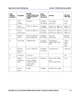
Controls
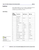
• The HEX switch (
SW1
) allows you to select the control parameters.
(
See
“Switch Settings” on page 168
.
)
• The
Adjuster
two-position up/down toggle switch (
SW2
) allows you
to adjust the parameter values.
• The
Service Push
button allows you to locate the position of the
particular module in the network when one or multiple VFS-6801 or
any other modules are linked together over a 75
Ω
network (DigiNet)
and connected to the central controller (PC or Leitch DigiNet panel).
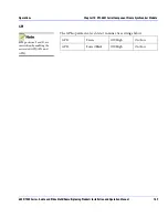
LED Indicators
• The
625 Auto 525 - 360, 270, 143
LEDs (green) show the standard as
follows: the
525/625
LEDs indicate a detected standard if the
Auto
LED is
On
and a forced line standard if the
Auto
LED is
Off
.
• The
Data Pres
LEDs
(green) lights to indicate that a valid source of
serial digital video is present at the input of the module.
• The
Service
LED (amber) lights for a short time upon power up but
remains off during normal operation. If the
Service
LED is blinking or
continuously on, a hardware failure has been detected.
Jumpers
• ICLK: The
ICLK
jumper is not used.
• OCLK: The
OCLK
jumper has to be installed.
• Frame ID:
Frame ID
is made possible by reading the silicon serial
number (if installed in the
RJ11
at the back of the frame). The two
jumpers are shipped in the
Off
position from the factory and must
both be in the
On
position to enable reading of
Frame ID
.