background image

9

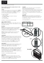
6.1.  Work environment and safety

Dangerous voltage, danger to 

life from electric shock:

If the housing is damaged

, the power cord must be disconnected from the 

power source immedi-

ately. Keep the 

device away 

from moisture and wet conditions. 

Before starting

, check the power 

cord, the plug

 and the extension cable for electrical and mechanical

 damage.

Fire and explosion hazard

Admixtures (e.g. combustible or explosive gases or vapors), traces of oil, oil vapor and grease must not 

be sucked in. Any 

operation in a potentially explosive environment

 is 

prohibited.

 The device must 

only be operated with the filter plate installed

.

No hazardous leak tracer is to be used for testing the weld seams. 

There is a 

risk of inhalation 

of

 liquid particles. Read the material safety data sheet from the manufacturer of the material and 

follow that company's instructions.

Risk of injury from plastic chips

 at startup. 

Damaged plastic glass

 can lead to 

implosion

. This may cause eye injuries. The plastic glass must 

be protected against mechanical damage by impact or fall, for example. Do not put a defective VACU-

UM PLATE into operation. 

Wear protective goggles.

Vacuum blower

 causes 

high noise levels. There is therefore a risk of hearing damage

 while 

operating the device. 

Wear hearing protection.

Risk of inhalation of dust particles

 while operating the device. If the membrane is contaminated, 

dust particles can be sucked in and ejected by the blower. The 

membrane

 must be 

free of impuri-

ties in the

 test area.

If the device is being used on construction sites, a 

fault current circuit breaker

 must be used to 

protect site personnel from electrical shock 

due to dampness and moisture.

Warning

6.  Operation of your VACUUM PLATE 300

Summary of Contents for 169.580

Page 1: ...Leister Technologies AG Galileo Strasse 10 6056 Kaegiswil Switzerland Tel 41 41 662 74 74 Fax 41 41 662 74 16 www leister com sales leister com VACUUM PLATE 300 English...

Page 2: ...7 5 3 Overview of device parts 8 6 Operation of your VACUUM PLATE 300 9 6 1 Work environment and safety 9 6 2 Preparation and operation 11 6 3 Test with VACUUM PLATE 11 7 Quick guide VACUUM PLATE 300...

Page 3: ...vapor and grease must not be sucked in Any operation in a potentially explosive environment is prohibited The device must only be operated with the filter plate installed No hazardous leak tracer is t...

Page 4: ...are of hazards in the surrounding area e g risk of tripping risk of slipping strong sunlight unattended equipment etc Note Caution 2 2 Non intended use 2 1 Intended use Any other use or any use beyond...

Page 5: ...Ambient temperature C F 10 60 14 140 Noise level LA LPA dB LWA dB 84 7 K 3 dB 95 7 K 3 dB Test pressure bar inHg 0 170 5 Weight kg lbs 7 7 17 a b c Dimensions a mm inches 750 29 5 b mm inches 250 9 8...

Page 6: ...mechanical damage The device must always be stored on a flat surface otherwise the sealing lip 7 can become permanently deformed Note Do not use the carrying handle 8 on the device for transporting wi...

Page 7: ...event of any inquiries to our representatives or authorized Leister Service Centers please always refer to this information Model Serial no 5 2 Scope of delivery Standard equipment in cardboard box 5...

Page 8: ...ressure setting valve Vari Flow valve 10 Type plate with model designation and series marking 11 Cooling openings 12 Suction air outlet 13 Device protective circuit breaker 1 Mains connection line 2 M...

Page 9: ...ial safety data sheet from the manufacturer of the material and follow that company s instructions Risk of injury from plastic chips at startup Damaged plastic glass can lead to implosion This may cau...

Page 10: ...g risk of tripping risk of slipping strong sunlight unattended equipment etc Note Caution 230 V up to 50 m 3 1 5 mm2 up to 100 m 3 2 5 mm2 120 V up to 50 m 3 1 5 mm2 up to 100 m 3 2 5 mm2 Power cord...

Page 11: ...tested with bothhandles 8 Turn on the main switch 2 on the VACUUM PLATE Turn the pressure setting valve Vari Flow Valve 9 clockwise until the desired or specified test pressure is set The existing ne...

Page 12: ...power supply cord 1 to the voltage source 2 Open the pressure setting valve Vari Flow Valve 9 turn counter clockwise to the stop 3 hold the device by the carrying handles 8 place it on the test locati...

Page 13: ...Flow Valve 9 Check the flatness of the membrane while pressing the VACUUM PLATE The VACUUM PLATE can compensate an unevenness of approx 10 mm via the sealing lip 7 There is a risk of leakage if there...

Page 14: ...ntact with aggressive substances e g acetone diluent etc There is a risk of damage to the installed components Recommended maintenance intervals for the device Note Dangerous voltage danger to life fr...

Page 15: ...65 EU Harmonized EN ISO 12100 2010 EN 60335 1 2012 A11 2014 A13 2017 AC 2014 Standards EN 55014 1 2017 A11 2020 EN 55014 2 1997 A1 2001 A2 2008 AC 1997 EN IEC 63000 2018 Kaegiswil 02 24 2022 Bruno von...

Page 16: ...y claim verification by invoice or delivery note manufacturing or processing errors will be rectified by the sales partner through replacement delivery or repair Heating elements are excluded from war...

Reviews: