background image

9

Rugby 200-3.2.1en

LED Indicators

LED Indicators

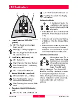
Rugby200-8 Rugby_membrane.eps

1 Laser Emission Indicator 

(yellow)

Off: The Rugby and the laser 
beam are off.

Flashing: Leveling in progress.

On: The Rugby has leveled and 
the laser beam is on.

2 Low Battery Indicator (red)

Off:  Battery ok 

Slow Flashing 1Hz: Low Battery

Fast Flashing 5Hz: Low Battery, 
turns off soon

On:  Turns off in 5 Minutes

3 Manual Mode Indicator (red)

Off: Automatic Self-Leveling 

Fast Flashing 5Hz: Manual, 
Cross Axis Self-Leveling

Slow Flashing 1Hz: Manual, Both 
Axes

4 Elevation Alert (H.I.) Indicator 

(red)

Off: The H.I. Alert function is off. 

On: The H.I. Alert function is on.

Flashing: H.I. Alert. The Rugby 
has moved.

Calibration Mode

In Calibration Mode, the 
Low Battery and Manual 
Mode Indicators will blink 
alternately.  

In the first axis the Low Battery will 
blink at 5 Hz, the Manual Mode at 
1 Hz.

In the second axis the Low Battery 
will blink at 1 Hz, the Manual Mode 
at 5 Hz.

When an arrow button is pressed to 
change calibration, the Emission 
Indicator LED will turn off for one half 
second to indicate a button press.

Out of Level Indication

When there is an Out of 
Level Failure, the Rugby 
has been set up outside 
of its self-leveling range 
and cannot achieve 
level. The LED’s will 

blink in sequence. Turn the unit off, 
level the top of the tripod and try again. 

If running line or grade in manual 
mode, the Rugby will also give an out 
of level indication if a limit is reached, 
reverse directions and continue 
working.

Summary of Contents for Rugby 200

Page 1: ...Rugby 200 User Manual Version 3 2 English...

Page 2: ...sult in death or serious injury CAUTION Indicates a potentially hazardous situation or an unintended use which if not avoided may result in minor or moderate injury and or appreciable material financi...

Page 3: ...own Calibration 19 Adjusting Laydown Calibration 19 Troubleshooting 20 Care and Transport 22 Transport 22 Storage 22 Cleaning and Drying Windows 22 Technical Data 23 Rugby 200 23 IR Remote Control 731...

Page 4: ...manual contains operating and set up procedures for common applications Its purpose is to describe the features of the Rugby 200 and how it operates This manual is not intended to describe specific ap...

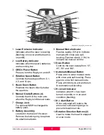
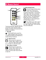
Page 5: ...attery pack 8 Battery Assembly Located in the base of the laser Remove the locking ring to replace the alkaline batteries 9 Manual Mode Indicator Flashes rapidly 5 Hz to indicate manual with cross axi...

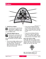
Page 6: ...is self leveling The Manual Mode Indicator will flash rapidly 5 Hz when in this mode Press the Auto Manual Button a second time to enter full manual mode The Manual Mode Indicator will flash slowly 1...

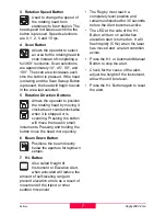
Page 7: ...scanning Pressing the button will move the head in small increments Pressing and holding the button move the head more quickly 6 Beam Down Button Positions the beam directly below the aperture for la...

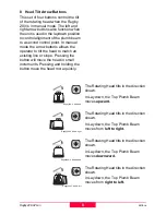
Page 8: ...line or slope Pressing the button will move the head in small increments Pressing and holding the button move the head more quickly Rugby200 4 Head up Rugby200 5 Head right Rugby200 6 Head down Rugby...

Page 9: ...ng H I Alert The Rugby has moved Calibration Mode In Calibration Mode the Low Battery and Manual Mode Indicators will blink alternately In the first axis the Low Battery will blink at 5 Hz the Manual...

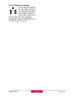
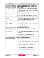
Page 10: ...Out of Temperature Range If the unit is set up and the environment is out of the specified operating temperature range all three LED s will turn on at the same time The operating temperature range for...

Page 11: ...switch 5 to turn the H I Alert on and off 3 Beam Down Function With the unit on press and hold the off on switch 4 then press the down arrow 6 switch to turn the beam down function on and off 4 Off On...

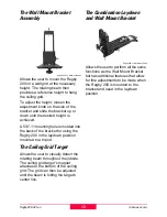
Page 12: ...ck of the bracket for using the Rugby 200 in the laydown position mounted to a tripod The Ceiling Grid Target Allows the user to visually detect the rotating beam throughout the jobsite The ceiling gr...

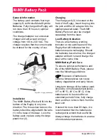
Page 13: ...the AC adapter into the appropriate wall outlet The NiMH Battery Pack can also be charged separately from the laser Low Battery Indication There is a low battery warning indicator on the switch panel...

Page 14: ...t take a charge check the following Check the AC input and DC output of the charger unit Check that the Rugby has a rechargeable pack installed Check charger cables for wear or damage Refer to your Ru...

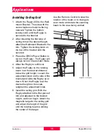
Page 15: ...ic mode 4 Allow the Rugby to self level 5 Adjust the Rugby so the rotating beam is at the desired distance below the grid height Loosen the adjustment knob on the side of the bracket and slide the Rug...

Page 16: ...General Construction The rotating beam creates a level plane of laser light over the entire jobsite that is used as a reference Used together with a Rod Eye handheld receiver or a machine mounted 360...

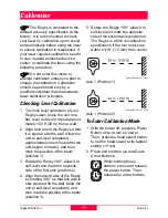
Page 17: ...unit to self level completely approximately one minute after the unit begins to rotate and then mark the position of the beam position 1 3 Rotate the Rugby 180 allow it to self level and mark the oppo...

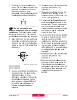
Page 18: ...ill turn off for one half second to indicate that a key has been pressed 6 Rotate the laser 180 and check the opposite side of Axis One position 2 7 Reposition the Rugby so that the handle is now poin...

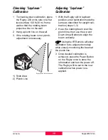
Page 19: ...ting Laydown Calibration 1 With the Rugby still in laydown position enter calibration mode the same as described for upright cali bration steps 1 3 2 Have the rotating beam scan the plumb line then us...

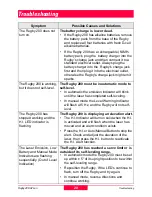
Page 20: ...l the laser has completed self leveling In manual mode the Level Warning Indicator will flash at 5 Hz and the Rugby will not self level The Rugby 200 has stopped working and the H I LED indicator is f...

Page 21: ...low battery LED is blinking The battery charge is low or dead See symption 1 above The Rugby is rotating at seven rps to indicate to the Rod Eye Pro that the laser has reached a low battery condition...

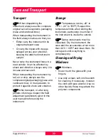
Page 22: ...original packaging case and cardboard box or its equivalent to protect it against shock and vibration After transport or after long periods of storage inspect the field adjustment parameters given in...

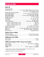
Page 23: ...R Article nr 732001 Serial nr 200 Class II 2 Operating Temperature 4 to 122 F 20 to 50 C Storage Temperature 40 to 158 F 40 to 70 C Battery Life 50 hours with alkaline 30 hours with NiMH Batteries Fou...

Page 24: ...ntinuous applications use of the Product Knockdown Warranty In addition to the standard Leica Geosystems 24 month warranty the internal self leveling system of the Rugby 200 is covered regardless of f...

Page 25: ...by rechargeable NiMH optional or Alkaline batteries The unit can be used with an infrared remote A plumb beam is generated by the unit for purposes of alignment Scan modes from 10 to 180 can be gener...

Page 26: ...the laser unit are responsible for developing implementing and communicating safety concepts for their products and are also responsible for the effectiveness of those safety concepts in combination...

Page 27: ...surements if the product is defective or if it has been dropped or has been misused or modified Precautions Periodically carry out test measurements and perform the field adjustments indicated in the...

Page 28: ...position the instrument on the tripod baseplate without securely tightening the central fixing screw If the screw is loosened always remove the instrument immediately from the tripod WARNING If the p...

Page 29: ...ll other functions and features are the same on each model Review the information below for the unit you have purchased The products are clearly identified by article number serial number and safety l...

Page 30: ...ts used on construction sites and outdoors surveying alignment leveling a Only qualified and trained persons should be assigned to install adjust and operate the laser equipment b Proof of qualificati...

Page 31: ...void direct eye exposure The accessible emission limit is within five times the accessible emission limits of Class 2 in the wavelength range from 400 nm to 700 nm WARNING Direct intrabeam viewing is...

Page 32: ...er beam should be termi nated at the end of its useful path and should in all cases be termi nated if the hazardous beam path extends beyond the limit hazard distance of the area in which the presence...

Page 33: ...man Service Code of Federal Regulations Class 2 II laser products Do not stare into the beam or direct it unnecessarily at other persons Eye protection is normally afforded by aversion responses inclu...

Page 34: ...eosystems cannot completely exclude the possibility that other equipment may be disturbed CAUTION There is a risk that disturbances may be caused in other equipment if the laser unit is used in conjun...

Page 35: ...tion If this equipment does cause harmful interference to radio or television reception which can be determined by turning the equipment off and on the user is encouraged to try to correct the interfe...

Page 36: ...which meets the International Standards of Quality Management and Quality Systems ISO standard 9001 and Environmental Management Systems ISO standard 14001 732987 3 2 1en Printed in Switzerland Copyr...

Reviews: