background image

3.6

Calibrating the Encoders

Calibration of the wheel encoder when using the DSX for the first

time is mandatory.

We recommend, to calibrate the wheel encoders at least once on

each scan site. In particular when ground conditions change - for

example, from asphalt to grass.

1.

Measure out a distance of exact 10 m. The defined distance is used

as a reference for the calibration procedure.

Ensure that the tablet is connected to the DSX.

2.

Turn on the DSX. Turn on the tablet and start the DXplore software.

3.

Start the calibration procedure with the DXplore software. Refer to

"Wheel encoder calibration".

4.

Move the DSX along the defined distance.

5.

Complete the calibration procedure with the DXplore software and

check the calibration result. If necessary, repeat the calibration.

After the prominent part on the outer wheel is worn out, it is

required to perform an encoder calibration. Lift one wheel during the

calibration procedure for a separate encoder calibration. Then repeat

the procedure with the other wheel. Compare the results with the

defined distance to ensure that both encoders work properly.

Calibration procedure

Setup

23

Summary of Contents for DSX

Page 1: ...Leica DSX User Manual Version 1 1 English ...

Page 2: ...e versions are marked and described Name Description Format DSX User Manual To operate the system to a basic level all instructions required are included in the User Manual Provides an overview of the system together with technical data and safety directions ü DSX Quick Guide Short introduction for setting up the DSX ü ü Refer to the following resources for all DSX documentation software the Leica...

Page 3: ...vice reports mySupport Create new support requests for your products that will be answered by your local Leica Geosystems Support Team View the complete history of your support requests and view detailed information on each request in case you want to refer to previous support requests myTraining Enhance your product knowledge with Leica Geosys tems Campus Information Knowledge Training Study the ...

Page 4: ...g and Adjusting the Handle 20 3 2 Attaching and Connecting the Laptop or Tablet 20 3 3 Inserting the Battery 21 3 4 Mounting the Pole Support Surveyor Kit Only 22 3 5 Switching the DSX ON OFF 22 3 6 Calibrating the Encoders 23 4 DXplore Software 24 4 1 Software Installation 24 4 2 Home Screen 24 4 3 Data Acquisition 27 4 4 Data Processing 30 5 Planning a Survey 34 6 Procedures for Working with the...

Page 5: ...evels of hazards and risks related to personal injury and property damage For your safety it is important to read and fully understand the fol lowing table with the different signal words and their definitions Supplemen tary safety information symbols may be placed within a warning message as well as supplementary text Type Description DANGER Indicates an imminently hazardous situation which if no...

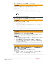
Page 6: ...roval of Leica Geosystems Inadequate safeguards at the working site 1 3 Limits of Use Suitable for use in an atmosphere appropriate for permanent human habita tion not suitable for use in aggressive or explosive environments WARNING Working in hazardous areas or close to electrical installations or simi lar situations Life Risk Precautions Local safety authorities and safety experts must be contac...

Page 7: ...not operated without the permission of the local authorities on frequencies and or output power levels other than those specifically reserved and intended for use without a specific permit the internal and external radio modems have been designed to operate on fre quency ranges and output power ranges The exact use of the frequency ranges differs from one region and or country to another DANGER Ri...

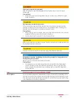
Page 8: ...attention During dynamic applications for example stakeout procedures there is a dan ger of accidents occurring if the user does not pay attention to the environ mental conditions around for example obstacles excavations or traffic Precautions The person responsible for the product must make all users fully aware of the existing dangers WARNING Unauthorised opening of the product Either of the fol...

Page 9: ...led to repair these products WARNING Inappropriate mechanical influences to batteries During the transport shipping or disposal of batteries it is possible for inap propriate mechanical influences to constitute a fire hazard Precautions Before shipping the product or disposing it discharge the batteries by the product until they are flat When transporting or shipping batteries the person in charge...

Page 10: ... Improper disposal If the product is improperly disposed of the following can happen If polymer parts are burnt poisonous gases are produced which may impair health If batteries are damaged or are heated strongly they can explode and cause poisoning burning corrosion or environmental contamination By disposing of the product irresponsibly you may enable unauthorised persons to use it in contravent...

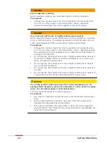
Page 11: ...rocedure ensure that the instrument is switched off and the battery has been removed CAUTION Unused connectors must be protected using the attached dust cap NOTICE Dropping misusing modifying storing the product for long periods or transporting the product Watch out for erroneous measurement results Precautions Periodically carry out test measurements and perform the field adjust ments indicated i...

Page 12: ...io or digital cellular phone devices in the vicinity of filling stations or chemical installations or in other areas where an explosion hazard exists Do not operate the product with radio or digital cellular phone devices near to medical equipment Do not operate the product with radio or digital cellular phone devices in aircrafts Do not operate the product with radio or digital cellular phone dev...

Page 13: ...out radio This device complies with part 15 of the FCC Rules Operation is subject to the following conditions This device may not cause harmful interference This device must accept any interference received Including interference that may cause undesired operation CAUTION Changes or modifications Changes or modifications to this unit not expressly approved by the party responsible for compliance c...

Page 14: ...cation to the FCC and coordination with existing authorized opera tions e The NTIA FCC coordination report shall include any needed constraints that apply to day to day operations Such constraints could specify prohibited areas of operations or areas located near authorized radio stations for which additional coordination is required before operation of the UWB equipment If additional local coordi...

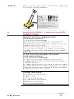
Page 15: ...e operated only when in con tact with or within 1 m of the ground This Ground Penetrating Radar Device shall be operated only by law enforcement agencies scientific research institutes commercial mining companies construction companies and emergency rescue or firefighting organizations NOTE IMPORTANTE POUR LES UTILISATEURS CANADIENS Canada Compliance Statement Numéro de certification 3177A CTDSX C...

Page 16: ...with DXplore software c GNSS antenna optional 2 3 Delivery Contents The delivered components depend on the package ordered The DSX system includes the following components DSX utility detection radar CMS1000 controller mount system AB1000accessory bag GEB242 battery GKL312 charger GEV192 9 AC DC adaptor GAS1000 grid assistance square USB card with User Manual Hex keys Configurable and region based...

Page 17: ...ing the distance travelled from the starting point of a scan The meas ured distance is constantly transferred to the DSX The encoders are positioned inside the rear wheels of the DSX to ensure correct measurements even in rough terrain Handle The handle of the DSX can be adjusted both in height and inclination The recommended inclination is indica ted with markers on the handle For easy transport ...

Page 18: ...rom 20 C to 50 C 4 F to 122 F Low operating temperatures reduce the capacity that can be drawn high operating temperatures reduce the service life of the battery Storage Remove batteries from the product and the charger before storing After storage recharge batteries before using Protect batteries from damp and wetness Wet or damp batteries must be dried before storing or use The batteries can be ...

Page 19: ...solute coordinates system and to receive real time positional correc tions while the DSX cart is moving and collecting data The antenna should fulfill the following requirements Multi frequency L1 L2 L5 Positioning update greater than 5 Hz Bluetooth RTK Real Time Kinematic reference station functionality RTK network Unlimited RTK range DGPS RTCM Refer to the equipment list for compatible models Fo...

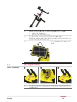
Page 20: ...569_001 1 2 3 4 1 Release inner cam levers and unfold upper handle legs 2 Lock inner cam levers until the visual markers are aligned 3 Release outer cam levers and raise entire handle assembly until the visual markers are aligned 4 Loosen the knobs to extend the upper handles and then tighten them 3 2 Attaching and Connecting the Laptop or Tablet The support is designed to hold a CT1000 tablet 001...

Page 21: ... to hold the two RAM balls Adjust the tablet cradle until optimal inclination and then tighten the screw on the double socket arm 3 xxxxxx_001 xxxxxx 001 0019637_001 Plug in the DSX LAN cable to the tablet 3 3 Inserting the Battery 0019570_002 1 2 3 1 To open the battery compartment loosen the screw on the battery compartment Insert the battery Setup 21 ...

Page 22: ...er to the upper chassis 2 Attach the two clamps to the pole 3 Make sure the clamps align so they can both fit into the brackets Tighten the screws of the clamps so they are stable on the pole 4 Place the lower clamp in the housing bracket and then fit the upper clamp in the handle bracket 5 Tighten the screw of the handle bracket 3 5 Switching the DSX ON OFF xxxxxx_001 xxxxxx_001 0019637_001 1 Pre...

Page 23: ...ablet and start the DXplore software 3 Start the calibration procedure with the DXplore software Refer to Wheel encoder calibration 4 Move the DSX along the defined distance 5 Complete the calibration procedure with the DXplore software and check the calibration result If necessary repeat the calibration After the prominent part on the outer wheel is worn out it is required to perform an encoder c...

Page 24: ...tablet DXplore software can be downloaded from myWorld Before running the software make sure to activate software license key entitlement ID in CLM program DXplore will not run without a valid software license key 4 2 Home Screen a Left column b Centre column c Right column Requirements for installing the DXplore software Home screen 24 DXplore Software ...

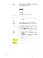
Page 25: ... marking Extend the folding square until the hard stop Place the folding square at the corner of your survey area and draw a right angle Mark every 50 centimeters until the full grid is marked on the surface Wheel encoder calibration Measure a 10 meter linear distance precisely Tap start and push your DSX radar cart until reaching the exact 10 meter end Make sure the red markers on the side are al...

Page 26: ...s units Choose the local unit imperial units for the US and metric units for the rest of the world Language Choose the required language from the drop down list Run in full screen Enables you to maximise the DXplore screen when reopen DXplore next time Button DSX inactive Button DSX active Button DSX indicates the connection status to the DSX utility detec tion system In active mode the button sho...

Page 27: ...ition once a GNSS antenna is used Button TPS inactive TPS is not supported yet 4 3 Data Acquisition From the project summary tap Go to Acquisition to get to the acquisition screen Refer to 6 Procedures for Working with the DSX for details There are two ways to get to the project summary Open a draft Open a draft by selecting from the right column of Home screen or searching from drive with Load Pr...

Page 28: ... should be green and not crossed out throughout the entire acquisition Note in the acquisition screen the button only indicates the status of GNSS connection To set up the GNSS antenna go to the Home screen for the wizard and open the project draft to continue the scan To be supported in the upcoming versions Indicates the battery level of the DSX utility detection system Fully charge the battery ...

Page 29: ...goes beyond the end point of the scan line the remaining distance becomes a warn ing If exceeding a certain distance and if the Stop Scan button is not tapped the software forces a stop to avoid distance calculation errors Tap Start Scan button before starting a new line Tap Stop Scan once the line is completed Acquisition DXplore Software 29 ...

Page 30: ...e is used for giving additional information on water sewer or drainage Lamp Post is a great indication of power cables Other Add POIs which do not belong to the listed types Once the data acquisition is completed tap Analyse Data to process the scan data The result is displayed and by default in animation in the next screen 4 4 Data Processing Tap the button Analyse Data on the top right of the ac...

Page 31: ...e Home screen 2D and 3D view button 2D view is the top view from above and sees the entire area in a flat view 3D view allows rotation to view utilities in various depths Zoom to and centre on grid Full extent to fit all added layers and the grid in the viewer DXplore Software 31 ...

Page 32: ...ons are available in the current POI list Electromagnetic Location is used to mark the positions where the cable locator detects signals Trench Scar is used to mark where the road surface has been opened and covered This option gives ideas where utilities may be buried Hydrant is used for giving additional information on water pipes Manhole is used for giving additional information on water sewer ...

Page 33: ...ort to MC1 Generates the detected utilities and scan area in DXF format under the MC1 compatible directory structure This file allows using the DXplore output directly on the excavator controlled by MC1 software by USB syncing Back to Acquisition Allows the operator to go back to the acquisition screen and rescan a few lines when a problem in tomography is spotted DXplore Software 33 ...

Page 34: ...n the way during the survey Technical maps of existing utilities are normally created by public utility com panies Such maps give a schematic overview about the type and position of utilities that are constructed and managed by the public utility companies Even if these maps are generic they can give a first impression of the existing utilities and provide additional information during the data ac...

Page 35: ... clearly marked 3 Calibrate the wheel encoders on the jobsite before proceed to scan Measure and mark precisely a 10 meter distance Open DXplore and tap on Wheel Encoder Calibration in the setup tutorial session in Home screen Follow the wizard to complete the calibration 4 Depending on the purpose of the survey and the available accesso ries carry out one of the procedures described in the follow...

Page 36: ...are 2 Start a scan 3 Enter project informa tion 4 Define scan size and approximate location The grid location and orientation can only be approximated by select ing 2 points on Google Maps 5 Tap Search on Maps 36 Procedures for Working with the DSX ...

Page 37: ...viewer Grid origin and orienta tion is displayed Zoom and pan in the viewer until reaching a preferred visualisation then tap Next Summary 8 Confirm the information of the project summary Save and close the draft for further scan or proceed to scanning 9 Make sure to have the grid physically marked on the ground surface Refer to the setup tutorial in Home screen Procedures for Working with the DSX...

Page 38: ...ront back and sides of the cart 3 Tap Start Scan and start pushing the cart forward 4 Precisely on top of the end point of the line tap Stop Scan to stop the cart 5 Once the full scan is ended tap Analyse Data Check and follow up of scans After tapping Analyse Data the tomography is generated The anima tion is on by default 1 Tap pause button to start marking utilities It is mandatory to check on ...

Page 39: ...e verifica tion process DXplore then verifies it 4 Utility found If availa ble make sure to enter the information cor rectly Depth is esti mated by the program 5 If the utility is not found there is still the option to keep it as an anomaly 6 View your utilities in 3D Procedures for Working with the DSX 39 ...

Page 40: ...ed utilities and scan area in dxf format under the MC1 com patible folder struc ture This allows using the DXplore out put directly on the excavator con trolled by MC1 soft ware by USB sync ing 6 3 Mapping Utilities Using a GNSS Antenna Performing a scan project This step by step procedure describes how to perform a scan from scratch This chapter gives information on how to Set up a project new sc...

Page 41: ...enna for the GG04 plus antenna 3 Start a scan 4 Enter project informa tion 5 Define scan size loca tion and to import his tory layers as reference if any 6 On site DXplore is automatically streaming the antenna posi tions Point the antenna pole tip to the grid corner and tap the Lock but ton This position is the bottom left corner Procedures for Working with the DSX 41 ...

Page 42: ...tility map in DXF format 8 It is mandatory to spec ify the coordinate sys tem of the DXF layer to position the utility map correctly The project coordinate system so is your grid corner coordinates changes to the same coordinate system 9 Zoom and pan in the viewer until reaching a preferred visualisation then tap Next Summary 10 Confirm the information of the project summary 42 Procedures for Work...

Page 43: ...e grid assistance square in DSX accessory bag to accu rate mark the grid on the ground surface 2 Do a site check Tap Add POI to add conspicuous points of interest on site 3 Adjust the cart position and direction using the arrows to coincides the conditions on site 4 Place the cart centre precisely on top of the starting point Use the four red markers in the front back and sides of the cart 5 TapSt...

Page 44: ... utilities The soft ware starts the verifica tion process It is mandatory to check on each slice to find utilities in that depth range 3 Tap Add utility and start marking the utility using your finger DXplore then verifies it 4 Utility detected If avail able make sure to enter the information correctly The software estimates the depth 44 Procedures for Working with the DSX ...

Page 45: ...marked 2 Tap on Export to export the project out put 1 Utility lines and POIs in DXF format Out put in grid based coordinate system 2 Current tomography in image formats 3 PDF report 4 Export to MC1 Gen erates the detected utilities and scan area in DXF format under the MC1 com patible directory structure This option allows using the DXplore output directly on the exca vator controlled by MC1 soft...

Page 46: ...ce the GS18 T antenna was found Now the connection to the GS18 T antenna is established Do not skip antenna configuration uncheck if the Real Time Kinematic RTK configuration has not been set up yet 9 Enter the PIN PUK APN of the cellular SIM card in the next screen Check if the connection is suc cessful 10 Enter the RTK service provider informa tion as requested Here we use SmartNet Once the user...

Page 47: ...rect Do not consider the bottom shift from the pole tip above ground 8 Tap Connect once the GS18 T antenna was found Now the connection to the GS18 T antenna is established Skip antenna configuration check DXplore reads the configuration from the GS18 T antenna Configuration of the GS18 T antenna is completed The real time position and accuracy is shown in 3D 9 Tap Use GNSS once satisfied with the...

Page 48: ...us in Win dows Password is 0000 2 Open the Leica Zeno Connect applica tion 3 Set up the Real Time Kinematic RTK corrections in Leica Zeno Connect Profiles Profile Name Description Internet connection configuration Enter details for new server Connect the GG04 plus antenna 48 Procedures for Working with the DSX ...

Page 49: ...ike to do Select a mountpoint RTK Correction Details 4 Once all Connection Status are checked the window automatically closes The positioning status of the GG04 plus antenna is shown in Leica Zeno Connect Procedures for Working with the DSX 49 ...

Page 50: ...re 2 Tap on the GNSS icon in the bottom bar of the Home screen The GG04 plus antenna should be shown in the DXplore GNSS connection window 3 Tap Connect 4 Enter the correct pole height Do not consider the bottom shift from the pole tip above ground Now the connection to the GG04 plus antenna is established The real time position and accuracy is shown 5 Tap Use GNSS once satisfied with the accuracy...

Page 51: ...6 The Home screen appears with the GNSS icon in green Procedures for Working with the DSX 51 ...

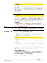
Page 52: ...ed before storing or use A storage temperature range of 0 C to 30 C 32 F to 86 F in a dry environment is recommended to minimise self discharging of the battery At the recommended storage temperature range batteries containing a 40 to 50 charge can be stored for up to one year After this storage period the batteries must be recharged 7 3 Cleaning and Drying WARNING Risk of electric shock during cl...

Page 53: ...Wet connectors must be dry before attaching the dust cap Connectors with dust caps Care and Transport 53 ...

Page 54: ...t 40 cm 50 cm Number of Hardware Channels 1 Antenna Central Fre quency 600 MHz Antenna Orientation Broadside antenna array in the direction which is perpendicular to the DSX moving direction Sampling Frequency 400 kHz Type Li Ion Voltage 14 8 V Capacity GEB242 5 8 Ah Typical operating time Measuring time 8 h Acquisition Speed Normal walking speed up to 7 km h Dimensions Weight Control unit Battery...

Page 55: ...rective Warning this equipment is destined for use in industrial environments Class A apparatus In residential commercial and light industry environments this apparatus may generate radio interference in this case the user may be required to operate while taking appropriate countermeasures The apparatus is sensitive to the presence of external electromagnetic fields which may reduce its performanc...

Page 56: ...ogether with all products and can also be refer red to and downloaded at the Leica Geosystems home page at http leica geosystems com about us compliance standards legal documents or collected from your Leica Geosystems distributor You must not install or use the software unless you have read and accepted the terms and conditions of the Leica Geosystems Software Licence Agree ment Installation or u...

Page 57: ......

Page 58: ... AG Heinrich Wild Strasse CH 9435 Heerbrugg Switzerland Phone 41 71 727 31 31 www leica geosystems com 900644 1 1 0en Original text 900644en 1 1 0 Published in Switzerland 2019 Leica Geosystems AG Heerbrugg Switzerland ...

Reviews: