13
3.
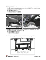
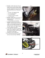
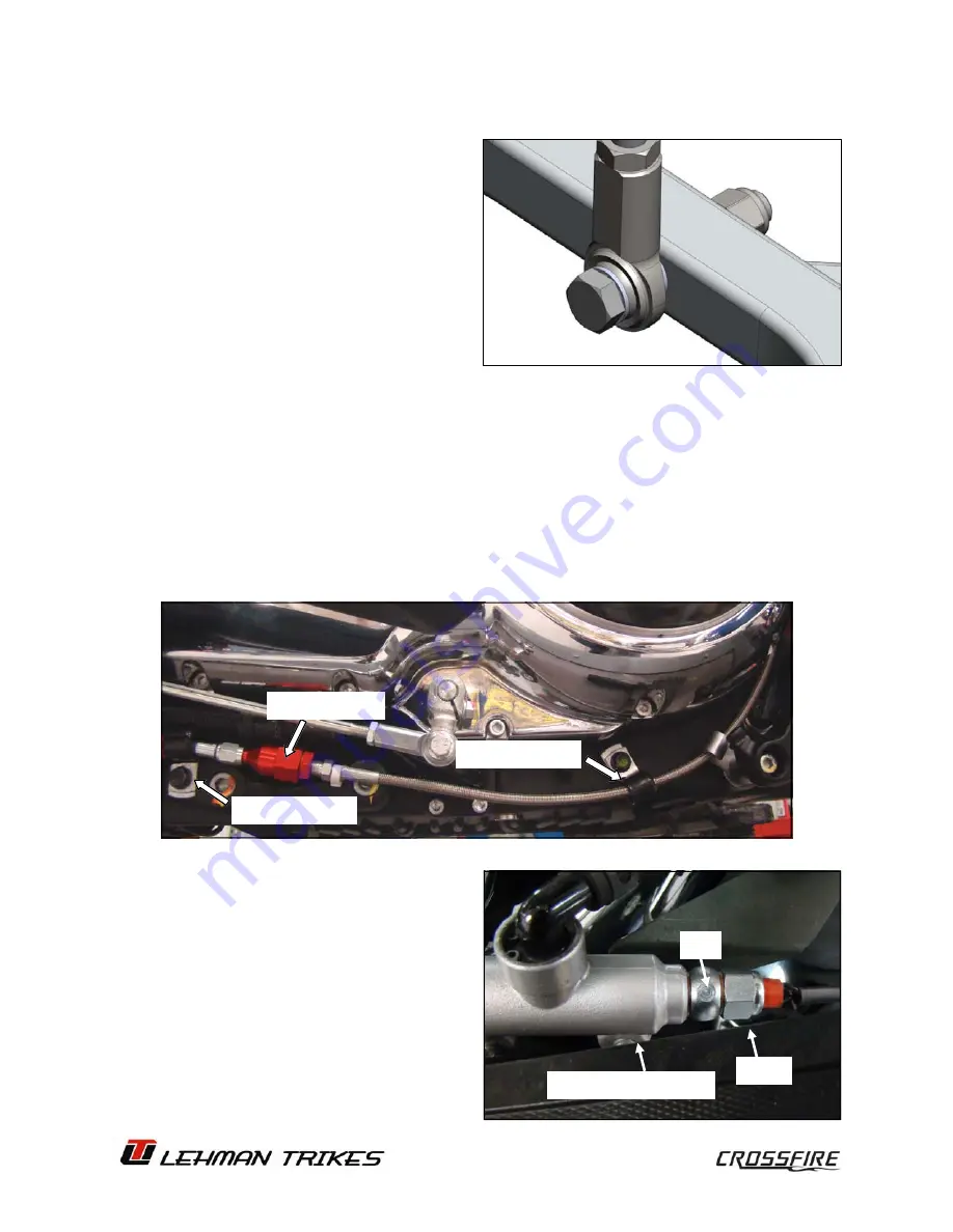
See Fig. 1
. Attach rod-end to right control arm
with the included hardware in the following
order: 3/8” x2-1/4” bolt, washer, rod-end,
washer, control arm, washer, and then nut.
Torque to
45 ft-lbs
.
•
(2) 3/8” x 2-1/4” Hex Head Bolts– CB2001
•
(6) 3/8” Thin Flat Washers– CW2182
•
(2) 3/8” Lock Nuts– CN3051
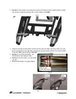
4. Adjust left side rod-end until it aligns with the
left control arm mounting hole.
5. Tighten jam nut on the left side rod end as-
sembly.
6. Attach rod end to left control arm just as was done to right control arm. Torque to
45 ft-lbs
.
Brakes
1.
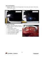
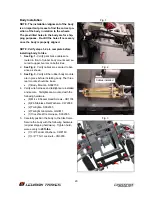
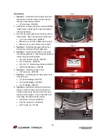
See Fig. 1
. Assemble the new brake lines and residual valve and install as shown using the fol-
lowing hardware. Route front of new brake line to master cylinder in original location.
•
(1) Rear Brake Line, 29”- S002367
•
(1) Front Brake Line, 23.5”- S002368
•
(1) Residual Valve- GB1146
•
(2) Clamps– S001654
2.
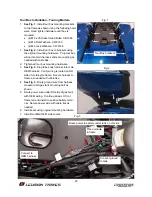
See Fig. 2
. Attach front brake line to master
cylinder with brake light switch.
•
(1) Brake Light Switch– S002369
•
(2) Banjo Washers– GC6002
Front line/clamp
Front line/clamp
Residual Valve
Fig. 1
Fig. 1
Fig. 2
OEM Master Cylinder
Switch
Line


