LEGRAND MIDDLE ATLANTIC FlexView 800 Series Instruction Sheet Download Page 11

Page 11

INSTALLING THE VESA 800 DISPLAY ADAPTER BRACKETS (OPTIONAL)

NOTE

: Only install the 

VESA 800 display adapter 

brackets if your display 

requires VESA 800 spacing.

For more information, refer 

to the documentation 

provided with your display.

NOTE

: Verify the torque on 

your power driver is on the 

lightest setting and only 

increase as necessary
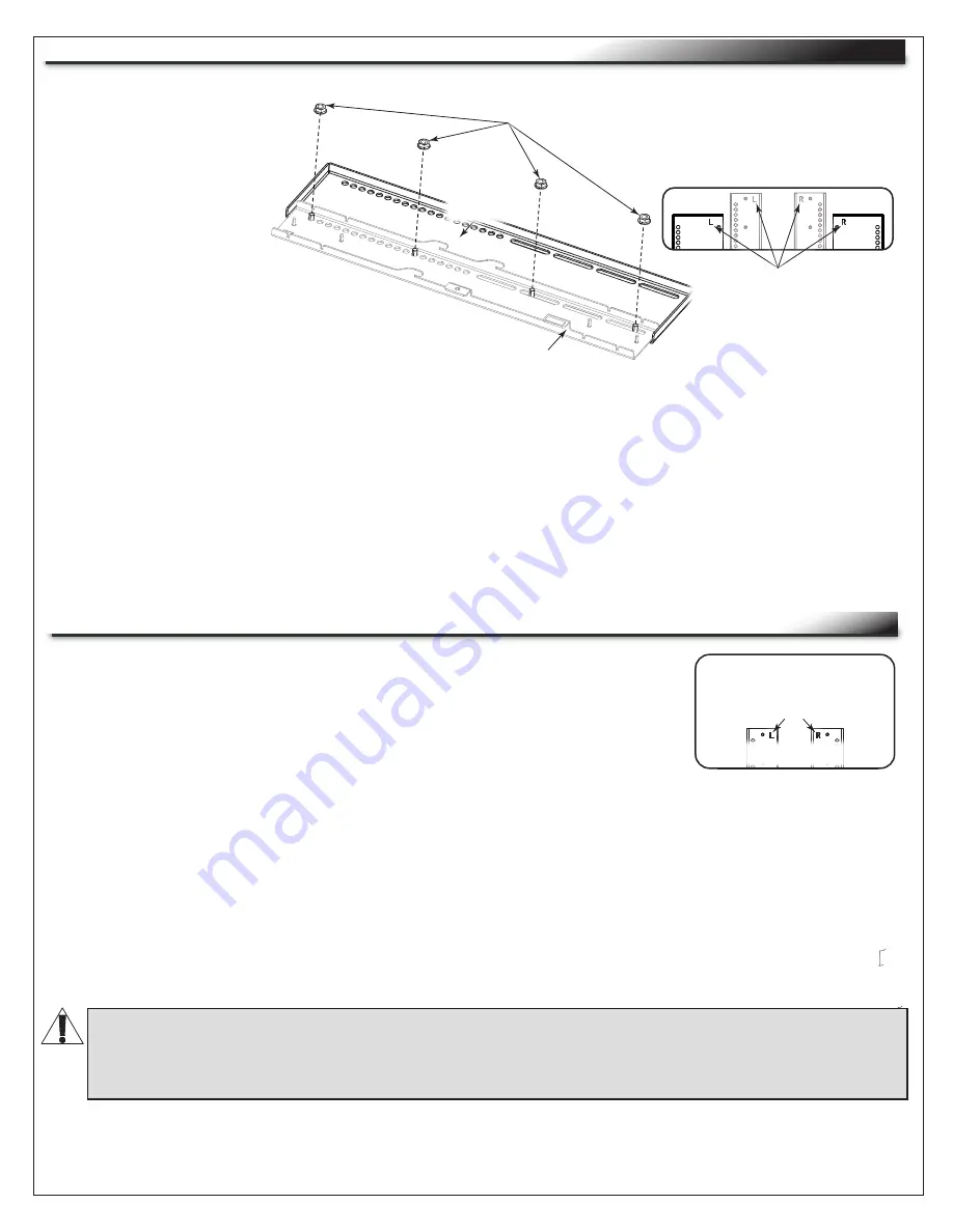
1. Place the left 

interface

 bracket   

  (punched with an “L”) over the   

  studs on the left VESA 800    

  adapter bracket (also punched   

  with an “L”) as shown. 

 (

FIGURE F

)

2. Use a power driver, ½” socket, and (4x) 5/16-18 flange nuts to secure  

  the brackets together.

3. Repeat the process with the right brackets (each punched with an “R”).

Interface 

Bracket

D

FIGURE F

NOTE

: The VESA 800 display adapter bracket 

and (4x) 5/16-18 flange nuts are shown in 

black for clarity.

Interface brackets and 

VESA 800 display 

adapter brackets are 

punched with “L” and 

“R” markings.

Flange 

Nuts

While brackets are attached to 

the rear of your display, they 

are considered left and right 

relative to viewing from the 

front.

VESA 800 

Display 

Adapter 

Bracket

ATTACHING INTERFACE BRACKETS TO THE BACK OF YOUR DISPLAY

1. Carefully place your display facedown onto an appropriate work surface.

2. Align the left and right interface brackets (labeled "L" and "R" 

  accordingly) with threaded inserts on the back of your display.

 (

FIGURE G

)

Interface brackets are 

punched with “L” and “R” 

markings.

FIGURE G

NOTE

:

• While brackets are attached to the rear of your display they are punched left and right relative to  


  viewing from the front.

• Center the 

interface

 brackets on your display so they do not extend past the top or bottom.

3. Determine the correct size pan head screws for attaching the interface brackets to your display. For  

  more information, see "Selecting Correct Interface Bracket Hardware for Your Display" on page 12.

4. Determine if spacers are required when attaching the interface brackets to the back of your display.  

  (

FIGURE H

)

5. Use a power driver, #2 Phillips bit, (4x) spacers (if required), (4x) washers, and (4x) correct length    

  pan head screws to attach the interface brackets to the back of your display as shown.

WARNING: 

Spacers must be used if your display has a recessed and/or uneven portion on the 

back where the threaded inserts are located. 

AVERTISSEMENT

:

 Des entretoises doivent être utilisées si votre écran a une partie en retrait 

et/ou inégale à l'arrière où se trouvent les inserts filetés.

Summary of Contents for MIDDLE ATLANTIC FlexView 800 Series

Page 1: ...odecs and smaller components Adjustable cable management included I 00669 Rev G FlexView 800 Series FVS Electric Lift Conferencing Cart Instruction Sheet Thank you for purchasing the FlexView 800 Series FVS electric lift conferencing cart Please read these instructions thoroughly before installing or assembling this product ...

Page 2: ...rect Interface Bracket Hardware for Your Display Page 10 Installing the VESA 800 Display Adapter Brackets Optional Page 11 Attaching Interface Brackets to the Back of Your Display Page 11 12 Attaching Your Display onto the Horizontal Mounting Bracket Page 12 13 Reversing the Door Page 14 Removing Lever Lock Plate and Channels Page 15 Changing Lever Lock Bracket Locations Page 15 Understanding Cabl...

Page 3: ...lectric shock Check with a qualified electrician or serviceman if you are in doubt as to whether the product is properly grounded Do not modify the plug provided with the product if it will not fit the outlet have a proper outlet installed by a qualified electrician DANGER un mauvais branchement du conducteur de terre de l équipement peut entraîner un risque de choc électrique Consultez un électri...

Page 4: ...ants peut traduire par de graves blessures des dommages à l équipement ou invalider la garantie Il est la responsabilité de l installateur utilisateur de s assurer que ce produit est chargé conformément aux spécifications AVERTISSEMENT Les caractéristiques de poids de ce produit peuvent être trouvées sur le produit Le dépassement de ces caractéristiques de poids peut entraîner des blessures graves...

Page 5: ...operate where aerosol spray products are being used or where oxygen is being administered 11 To disconnect turn all controls to the off position then remove plug from outlet 12 For chairs and similar furnishings with movable parts such as foot supports the following statement WARNING Risk of Injury Keep children away from extended foot support or other similar parts 13 WARNING Risk of Electric Sho...

Page 6: ... lieux où des produits aérosols sont utilisés ou à proximité d une source d oxygène 11 Pour débrancher placer tous les boutons en position off puis retirer la fiche de la prise électrique 12 Les chaises et meubles similaires dotés de pièces mobiles comme les repose pieds doivent être accompagnés de la déclaration suivante AVERTISSEMENT Risque de blessure Ne pas laisser les enfants s approcher d un...

Page 7: ... Load 20 lbs 9 kg Maximum Total Rated Load 190 lbs 98 kg Maximum Total Rated Load Item Weight Rating FlexView Conferencing Cart Inside of FlexView Conferencing Cart Display 40 1016 mm to 90 2286 mm Not Included Camera Not Included Soundbar Not Included Display Including any customer provided devices on optional camera mount and or soundbar mount WARNING This product is intended for use only with t...

Page 8: ...rotective Eyewear Power Driver 2 Phillips Screwdriver 2 Phillips Bit Slotted Screwdriver Level Toothpick or Small Straw Socket 5 16 Socket Socket Wrench Adjustable Wrench INSTALLING THE LEVELING FEET OPTIONAL 3 Repeat the process to remove all 4 casters from your cart NOTE You can remove the 4x pre installed casters on the bottom of your FlexView Conferencing Cart and replace them with the provide...

Page 9: ... cart is moved unplug the mains cable to installed equipment FIGURE C Page 9 4 Use power driver socket and 4x nuts from the previous steps to install a leveling foot A to the bottom of your cart FIGURE C 5 Repeat the process to install all 4 leveling feet to your cart 6 Make initial adjustments to the leveling feet by tightening retracting or loosening extending them as necessary 7 Place level on ...

Page 10: ...ing your display Refer to instructions I 00875 for Camera Mount and I 00876 for Soundbar Mount The interface hardware kit provided includes different pan head screw lengths to accommodate the threaded inserts on the back of most displays This topic helps you select the correct size pan head screws length for your display FIGURE E CAUTION Only use screws shorter than the mark or damage to the displ...

Page 11: ... OF YOUR DISPLAY 1 Carefully place your display facedown onto an appropriate work surface 2 Align the left and right interface brackets labeled L and R accordingly with threaded inserts on the back of your display FIGURE G Interface brackets are punched with L and R markings FIGURE G NOTE While brackets are attached to the rear of your display they are punched left and right relative to viewing fr...

Page 12: ...nterface Brackets Side of Display 3 Slowly lower the display while ensuring hooks and locking brackets on the top and bottom of both interface brackets fully engage onto the horizontal mounting bracket Side of Horizontal Mounting Bracket FIGURE K Locking Brackets on Interface Brackets Shown in black for clarity FIGURE J WARNING The hardware used must be assembled in the arranged order shown in thi...

Page 13: ...ontage horizontal Notches on Horizontal Mounting Bracket FIGURE L 5 Press the UP arrow button and raise your display to the highest position For more information see Understanding Some Operational Items on page 9 6 Raise both locking brackets to their highest position and then use power driver 2 Phillips bit adjustable wrench 2x 10 32 x interface bracket locking screws and 2x 10 32 flange nuts to ...

Page 14: ...e process for the other door 4 Use power driver and 2 Philips bit to remove 2x screws and the catch for the lower door only from the left side of the cart and install it to the corresponding location on the right side REVERSING THE DOOR 11 Hand tighten the display leveling screw you did not use for your leveling adjustment and then use the slotted screwdriver or 5 16 socket and wrench to tighten t...

Page 15: ...der to do this you must temporarily remove any devices cables and cable management from inside your cart and then remove Lever Lock plate and channels as explained in the previous topic 1 Temporarily remove any devices cables and cable management from the inside of your cart 2 Remove Lever Lock plate and channels as explained in the previous topic 3 Use a power driver or wrench and a 5 16 socket t...

Page 16: ...ble Clip Grooves Plug cable into appropriately rated receptacle Cable 8 32 Pan Head Screw Cable Management Clip 1 Raise display to highest position before securing cables For more information see Understanding Some Operational Items on page 9 2 Create a service loop to assure adequate cable length when display is fully extended FIGURE T 3 Secure cables into mounting holes and grooves using cable c...

Page 17: ...766 9770 F 888 599 5009 ca middleatlantic com av canada customerservice legrand com Middle Atlantic EMEA Technical Support P 31 495 726 003 av emea middleatlantic support legrand com Factory Distribution United States New Jersey California and Illinois Canada Ontario The Netherlands Weert At Legrand AV Inc we are always listening Your comments are welcome Legrand AV is an ISO 9001 and ISO 14001 Re...

Page 18: ......

Reviews: