


6)
Cycle the power when prompted.
b) RS232:
Scope requirements:
-
9-pin serial null modem cable connected to the PC.
-
From the scope utilities menu; select the GPIB/RS232 menu.
-
Select RS232; 8 bits; parity none; stop bits 1; max baud rate 19.2K; and ignore the GPIB address.
-
Place scope in stop mode by depressing STOP on
the front panel.
PC requirements:
-
Windows 95, 98, or NT operating system
-
LeCroy Scope Explorer utility.
-
Two 1.44 M byte formatted floppy disks
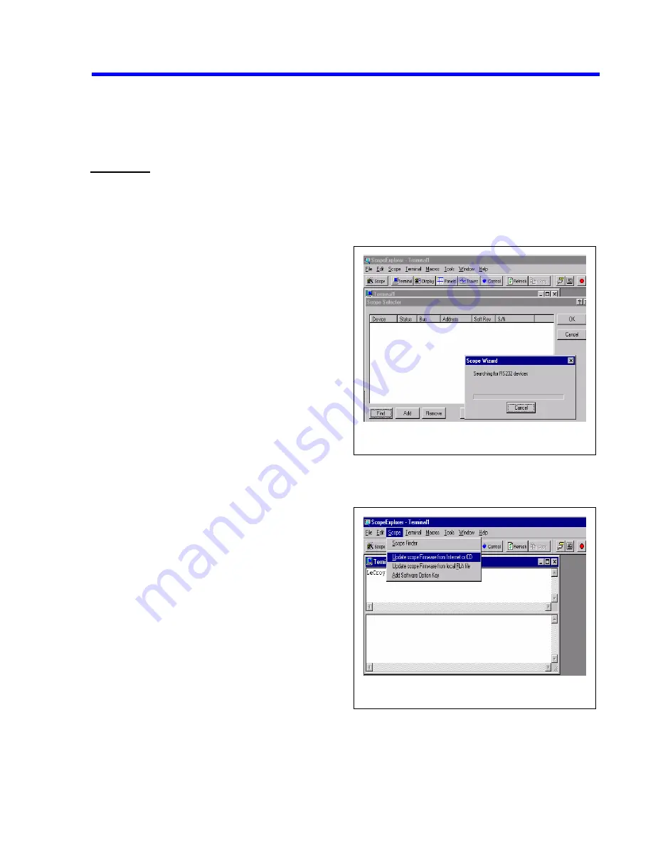
Connecting to PC
1)
Open Scope Explorer, then select Scope-finder
from the scope pull-down menu (see fig. #1)
2)
From the Scope-finder window select find.
3)
If more than one device appears in the window,
select the correct device.
4)
Using the scope pull-down menu select upgrade
DSO from internet/CD and follow the upgrade wizard (see fig. #2)
5)
The scope cannot be upgraded directly through RS232, but will download the firmware to 1.44
Mbyte floppy disks.
Figure 1: scope find window
Figure 2: firmware upgrade window
6)
After the software is loaded to the floppy disks,
put floppy # 1 into the scope drive.
7)
Push the utilities button and select special modes
from the on screen menu.
8)
Now select firmware update, and update from
floppy.
9)
From the on screen menu choose update flash.
10)
Remove floppy # 1 and insert floppy # 2 into
scope when prompted on scope display.
11)
Cycle the power when prompted.
Maintenance
6-7
Summary of Contents for LC564DL
Page 12: ...x Table of Contents ...
Page 18: ...2 4 General Information ...
Page 46: ...4 22 Theory of Operation 4 6 2 Power Supply Block Diagram ...
Page 59: ...Performance Verification 5 13 ...
Page 70: ...5 24 Performance Verification ...
Page 95: ...Performance Verification 5 49 ...
Page 115: ...Performance Verification 5 69 ...
Page 122: ...5 76 Performance Verification Figure 5 14 1MΩ Ω Ω Ω Rise time Equipment Setup ...
Page 148: ...6 14 Maintenance 6 6 4 Fan Problem ...
Page 149: ...6 6 5 Power Supply Voltages Problem Maintenance 6 15 ...
Page 150: ...6 16 Maintenance 6 6 6 Display Problem ...
Page 151: ...6 6 7 Front Panel Controls Do not Operate Maintenance 6 17 ...
Page 152: ...6 18 Maintenance 6 6 8 Remote Control GPIB or RS232 Problem ...
Page 153: ...6 6 9 Performance Verification Fails Maintenance 6 19 ...
Page 154: ...6 20 Maintenance 6 6 10 Floppy Disk Drive Problem ...
Page 155: ...6 6 11 Graphic Printer Problem Maintenance 6 21 ...
Page 156: ...6 22 Maintenance 6 6 12 Centronics Problem ...
Page 157: ...6 6 13 Hard Disk Drive Problem Maintenance 6 23 ...
Page 158: ...6 24 Maintenance ...
Page 181: ...Mechanical Parts 8 1 8 Mechanical Parts Figure 8 1 LC564DL Cabinet ...
Page 182: ...8 2 Mechanical Parts Figure 8 2 LC564DL Chassis Assembly ...
Page 184: ...8 4 Mechanical Parts Figure 8 3 Power Supply Installation ...
Page 185: ...Mechanical Parts 8 5 Figure 8 4 Lower Cover Assembly ...
Page 187: ...Mechanical Parts 8 7 Figure 8 5 Lower Cover Assembly with CKTRIG Option ...
Page 188: ...8 8 Mechanical Parts Figure 8 6 Lower Cover ...
Page 190: ...8 10 Mechanical Parts Figure 8 7 CKTRIG Option ...
Page 191: ...Mechanical Parts 8 11 Figure 8 8 Rear Panel Assembly ...
Page 193: ...Mechanical Parts 8 13 Figure 8 9 900079 Main Board Assembly ...
Page 194: ...8 14 Mechanical Parts Figure 8 10 900079 Main Board Assembly ...
Page 196: ...8 16 Mechanical Parts Figure 8 11 Upper Shield Assembly ...
Page 197: ...Mechanical Parts 8 17 Figure 8 12 Front Frame Assembly ...
Page 199: ...Mechanical Parts 8 19 Figure 8 13 Keypad Assembly ...
Page 200: ...8 20 Mechanical Parts Figure 8 14 Fan Assembly ...
Page 202: ...8 22 Mechanical Parts Figure 8 15 Graphic Printer Assembly ...
Page 203: ...Mechanical Parts 8 23 Figure 8 16 Upper Cover Assembly ...
Page 205: ...Mechanical Parts 8 25 Figure 8 17 Hard Disk Assembly ...
Page 206: ...8 26 Mechanical Parts Figure 8 18 Centronics VGA Interface Assembly ...
Page 207: ...Mechanical Parts 8 27 Figure 8 19 Floppy Disk Assembly ...
Page 209: ...Mechanical Parts 8 29 Figure 8 20 LC564DL Dimensions ...
Page 210: ...8 30 Mechanical Parts Figure 8 21 LC564DL Packaging ...


