The User Interface
User’s Manual Switchos
D850R3
3-3
3.3
Controls on the Front and Rear Panel
When the Switchos Advanced Microcolumn Switching Unit is used on a local
basis, the user sets the desired operating conditions via the controls on the front
panel and the push button and switch located on the rear panel. The present
status of the system is indicated by a series of LEDs on the front panel. The
loading pump is controlled via the keypad on the lower front panel of the
Switchos (see Section 3.5).
This section describes the use of the various controls and LEDs on the Switchos.
Basic information about how to use the keypad of the loading pump is presented
in Section 3.5, and detailed information is presented in the ‘UltiMate Micropump
User’s Manual’.
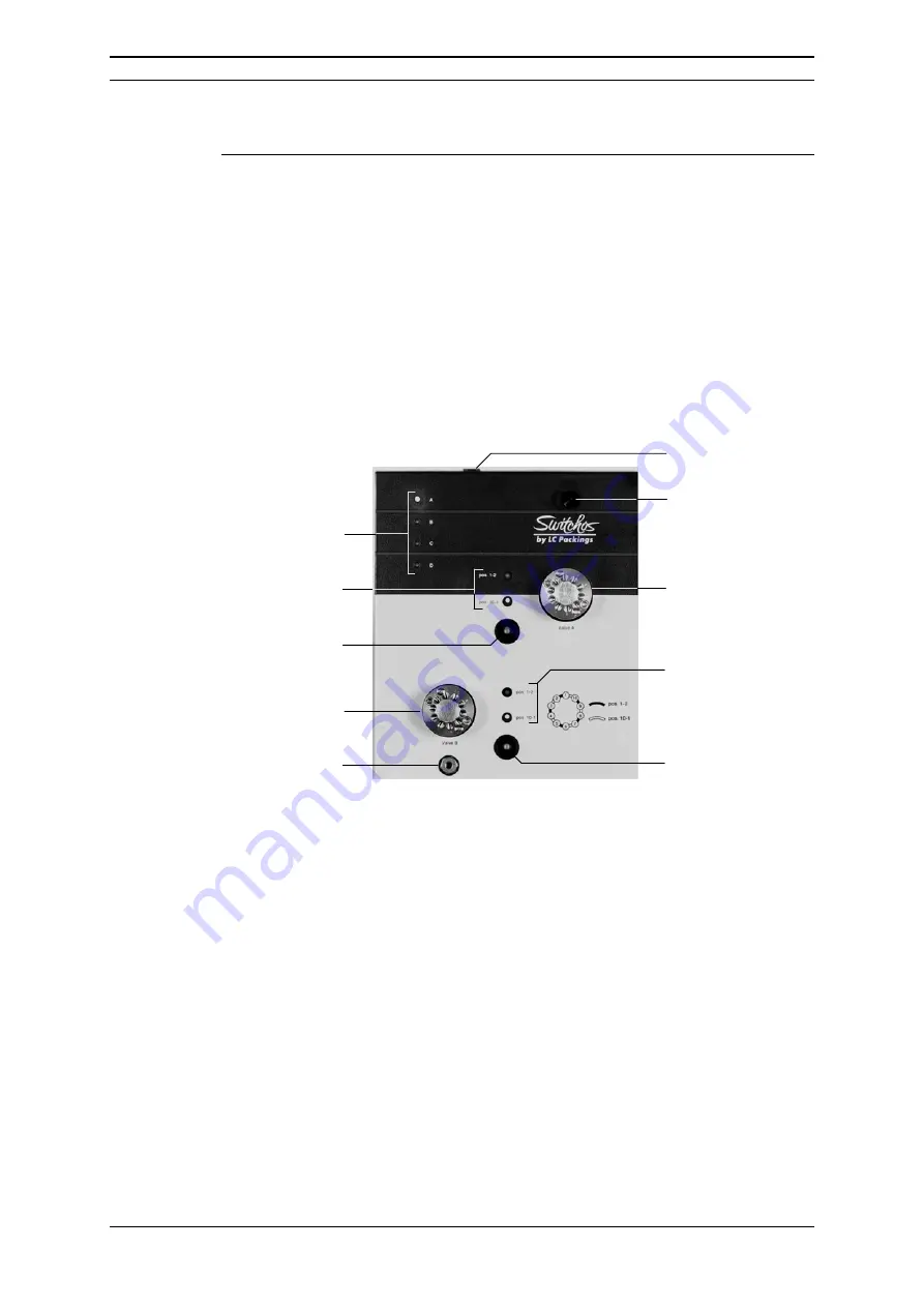
The
upper front panel
of the Switchos (FIGURE 3-3) includes the following:
ON/STANDBY
Switch
Button with LED
Valve A
LEDs
Valve B
Button with LED
Valve B
LEDs Solvent
Selection Valve
He Regulating
Valve
Valve A
Valve B
LEDs
Valve A
Microflow Outlet
FIGURE 3-3 Control Elements on the Upper Front Panel
•
Valve A and B Controls
– the 10-port switching valves can be controlled by
two push buttons when the Switchos is set into local mode. The local mode
is indicated by the built-in LEDs. Pressing the appropriate button will toggle
the position of the corresponding valve.
•
LEDs - Valve A
– indicate the position of valve A. When Valve A is switched
into position “1-2” (e.g. the fluidic connection is between inlet 1 and inlet 2,
the upper LED (1-2) is illuminated).
•
LEDs - Valve B
– indicate the position of valve B. When valve B is switched
into position “1-2” (e.g. the fluidic connection is between inlet 1 and inlet 2,
the upper LED (1-2) is illuminated).
•
LEDs - Solvent Selection Valve
– indicate the solvent bottle from which
solvent is being withdrawn at the present time.
•
He Regulating Valve
– used to control the flow of He for sparging (see
Section 2.5).
Summary of Contents for SWITCHOS II
Page 6: ...Table of Contents iv D850R3 User s Manual Switchos II This page intentionally left blank...
Page 14: ...CE Declaration xii D850R3 User s Manual Switchos II This page intentionally left blank...
Page 22: ...Introduction 1 8 D850R3 User s Manual Switchos II This page intentionally left blank...
Page 80: ...The Switching Valves A 4 D850R3 User s Manual Switchos II This page intentionally left blank...
Page 82: ...Network Identification B 2 D850R3 User s Manual Switchos II This page intentionally left blank...


