The User Interface
User’s Manual Switchos
D850R3
3-5
3.5
Basic Operations for the Loading Pump
The main screen of the loading pump includes a series of parameters that are
used to set the principal operating conditions for delivering the mobile phase,
such as the flow rate and maximum pressure. In automated mode (networking)
these parameters are set via CHROMELEON. The following sections provide basic
information about the loading pump, a detailed discussion on pump control is
presented in the ‘UltiMate Micropump User’s Manual’.
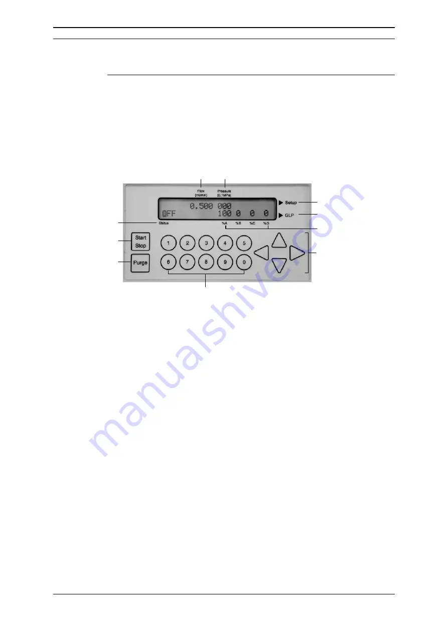
All communication between the user and the system is provided by the front
panel of the pump (FIGURE 3-5).
6
7
9
10
2
1
3
8
5
4
1 START/STOP
Purge
2 START/STOP
Pump
3
Status of Pump
4 Flow
Rate
5 Pressure
6
Setup Menu Access
7
GLP Menu Access
8
% value for solvents
(not used)
9
Arrow Keys for Cursor
10 Data Input Keys
FIGURE 3-5 The Front Panel of the Loading Pump
3.5.1.
Setting the Flow Rate
To set the flow rate, use the arrow keys to move the cursor to the
Flow
field
(item 4, FIGURE 3-5) and enter the desired flow rate.
3.5.2 Setting the Maximum Pressure
The maximum pressure value for the pump can be set via the Pressure field (item
5, FIGURE 3-5). As an alternative, it can be set via the PRESSURE LIMITS screen
of the SETUP Menu (global setting, see ‘UltiMate Micropump User’s Manual’).
To set the maximum pressure, move the cursor to the Pressure field (item 5,
FIGURE 3-5) and enter the desired value. When this field is being edited, it is
bracketed by a pair of vertical lines to indicate that this is a programmed value
rather than the actual pressure. During operation of the pump, the actual
pressure is indicated. However, if the cursor is moved to the Pressure field during
operation, the maximum pressure value will be indicated and the brackets will be
presented.
Summary of Contents for SWITCHOS II
Page 6: ...Table of Contents iv D850R3 User s Manual Switchos II This page intentionally left blank...
Page 14: ...CE Declaration xii D850R3 User s Manual Switchos II This page intentionally left blank...
Page 22: ...Introduction 1 8 D850R3 User s Manual Switchos II This page intentionally left blank...
Page 80: ...The Switching Valves A 4 D850R3 User s Manual Switchos II This page intentionally left blank...
Page 82: ...Network Identification B 2 D850R3 User s Manual Switchos II This page intentionally left blank...


