


48
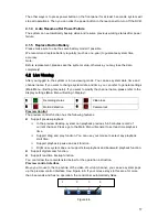
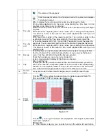
Figure 3-1
Please refer to the following sheet and Figure 3-1 for detailed information.
In the second line,
from the left to the
right,: 1
,
2
,
3
,
4
,
5
,
6
,
7
,
8.
ALARM 1 to ALARM 8. The alarm becomes active in low voltage.
In the first line, from
the left to the right:
1-NO C
,
2-NO C
,
3-NO C
There are three groups of normal open activation output (on/off
button)
Earth cable.
485 A/B
485 communication port. They are used to control devices such as
PTZ. Please parallel connect 120T
Ω
between A/B cables if there are
too many PTZ decoders.
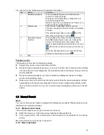
The 16-channel interface is shown as in Figure 3-2.
Figure 3-2
Please refer to the following sheet and Figure 3-2 for detailed information.
In the second line,
from the left to the
right,: 1
,
2
,
3
,
4
,
5
,
6
,
7
,
8.and the
first line from the left
to the right : 9
,
10
,
11
,
12
,
13
,
14
,
15
,
16
ALARM 1 to ALARM 16. The alarm becomes active in low voltage.
In the first line, from
the left to the right:
3-NO C
,
and the
second line from the
left to the right 1-
NO C
,
2-NO C.
There are three groups of normal open activation output (on/off
button)
Earth cable.
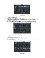
AB cable
connection
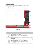
AB cable
connection
Summary of Contents for DH-D20004
Page 46: ...36 Figure 2 15 ...
Page 63: ...53 1U series 1 5U Series ...
Page 64: ...54 2U Series Figure 3 6 ...
Page 85: ...75 Figure 4 28 Figure 4 29 Figure 4 30 ...
Page 93: ...83 Figure 4 46 ...
Page 133: ...123 Figure 5 66 ...
Page 138: ...128 Figure 6 11 ...
Page 200: ...190 Samsung HA101UJ CE 1T SATA ...