Superabrasive
User
Manual
Original
Language
Lavina®
30G
‐
S
6/2014
10
4. OPERATION
PRELIMINARY
CONTROLS
Inspect
the
working
area
as
explained
in
the
safety
instructions.
For
wet
use,
fill
in
the
water
tank
or
connect
the
vacuum
extractor
and
ensure
that
the
vacuum
hose
is
clear
and
it
will
follow
the
machine
easily.
Make
sure
the
bonnet
air
filter
on
top
of
the
engine
is
clean.
It
should
be
cleaned
hourly.
Check
the
engine
oil
level,
screw
the
dipstick
in
to
get
reading.
See
to
it
the
tank
is
fill
up
(see
also
“Storage
Propane
tanks).
TANK
and
FUEL
LINES
‐
The
tanks
has
already
been
covered
but
do
the
fuel
lines
show
any
sign
of
wear
and
tear,
such
as
cracks
or
any
corrosion.
Screw
the
brass
fuel
line
fitting
onto
the
tank
service
‐
valve
hand
tight
only.
This
connection
MUST
be
secure
because
the
service
valve
has
a
safety
valve
inside
it,
which
will
only
open
if
the
brass
fuel
‐
line
fitting
is
COMPLETELY
seated
into
the
service
valve.
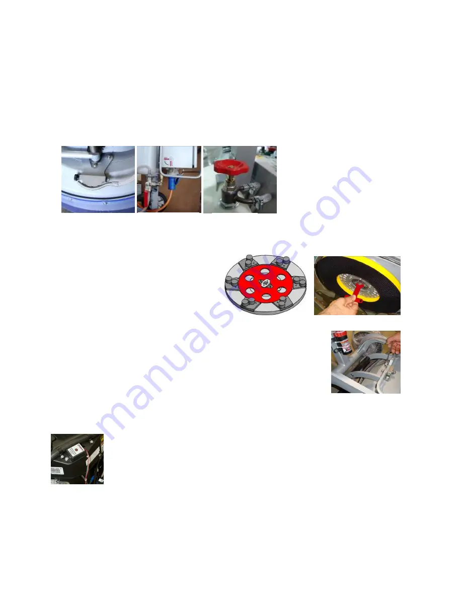
WATER
FLOW
CONTROL
UNIT
The
operator
can
choose
the
water
sprayer
in
the
front
when
the
tap
is
in
the
horizontal
position
(Fig.4.1),
the
water
will
spray
under
the
cover
of
the
machine
when
the
level
is
in
the
vertical
position
(Fig.4.2).The
flow
regulating
valve
located
on
the
tank
(Fig.4.2.1)
is
increasing
or
reducing
the
water
flow
to
the
working
area
–
in
front
of
the
machine
or
under
the
main
head
cover
of
the
machine/only
for
machines
produced
after
2013/.
ADJUSTING
AND
MOUNTING
TOOLS
Mount
the
tools
only
after
ensuring
that
there
is
enough
diamond
bond
material
left.
Be
sure
that
the
plates
are
always
clean
before
mounting.
WARNING:
Always
Secure
the“Quickchange”
pads
with
the
security
plate
(Fig.4.3),
lock
with
the
tool
holder
key
(Fig.5.3).
Diamond
tools
with
Velcro
are
attached
on
three
foam
plates
of
9
inch
(Fig.4.4).
The
foam
plates
are
ounted
on
the
key
lock
(butterfly).Always
use
the
tool
holder
key
(Fig.5.3).
FRAME
BLOCKING
(U
‐
JOINT]
The
relation
between
the
working
head
and
the
trolley
is
the
frame
u
‐
joint,
which
allows
rotation
about
two
perpendicular
axes
to
better
follow
the
profile
of
the
floor.
The
movement
along
the
one
axis
can
be
fixed
with
two
screws
(Fig.4.5)
and
that
block
the
lateral
movement
of
the
machine.
ALARM
EnviroGard
employs
a
sensor
(Fig.
4.6)
in
the
exhaust
path
between
the
engine
and
the
catalytic
muffler
to
detect
the
oxygen
content
of
the
exhaust
before
it
is
passed
through
the
catalyst.
The
oxygen
sensor
does
not
react
to
nor
does
it
measure
the
CO
content
of
the
exhaust.
It
responds
only
to
oxygen
content.
The
Control
Module
is
set
to
ignore
the
readings
from
the
oxygen
sensor
during
the
first
three
minutes
the
engine
is
running.
This
period
allows:
The
sensor
to
reach
a
stable
operating
temperature.
The
catalyst
in
the
muffler
to
reach
the
temperature
necessary
to
reduce
the
levels
of
CO,
nitrogen
oxides
(NOx)
and
hydrocarbons
(HC)
in
the
exhaust.
The
most
common
event
in
which
the
Control
Module
shuts
down
an
engine
is
when
the
air
filter
becomes
dirty
enough
to
restrict
the
air
intake
flow,
which
changes
the
air
‐
fuel
ratio
such
that
the
oxygen
sensor
signal
is
outside
the
control
limits.
Once
the
air
filter
is
properly
cleaned,
operation
of
the
machine
can
be
resumed.
Figure 4.4
Figure 4.3
Figure 4.5
Figure 4.2.1
Figure 4.1
Figure 4.2
Figure 4.6


