


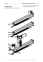


LAUNCH
440(440W) 455(455W) Installation Manual
20
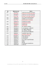
No
Material code
Name
1
201020712
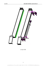
FL column
2
201020698
Locking latch plate assembly
3
103030114
Hexagon nut C class M20 GB41-86
4
103040138
Washer C class 20 GB95-85
5
103030143
Thin nut A,B class M20 GB6172-86
6
103100080
Quick L type air fitting APL8-02
(
for FRL
UNIT
)
103100215
Quick T type fitting APE6
(
440W
、
455W
)
7
102160383
FRL UNIT WAW2000-02
8
103201926
Manual solenoid valve
(
auto reset
)
TSV98322S
103100214
Quick L type air fitting APL6-02
(
solenoid
valve
)
9
103201504
Bracket of air valve
10
104090094
Quick hose fitting AD34.5 ZD-SM
11
103020133
Screw M10*25 GB/T5780-86
12
103040122
Flat washer 10 GB/T93-87
13
103040123
Spring washer 10 GB/T95-85
14
201011363
Bracket of power unit
15
103020134
Screw M6*15 GB/T5789-86
16
103990154
Power unit
(
220/380V 50/60HZ
)
17
103201512
Turn around fitting
18
201020708
Right column
19
201020711
Rear column
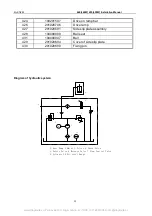
20
103250169
Name plate
21
103010481
Rivet 3*6 GB/T867-86
www.diagtools.eu, Pernavas 43A, Riga, Latvia, LV-1009, +37129416069, info@diagtools.eu