


Initial Setup
XR700T 2/28/22
3-2
Initial Setup
Hose Spring Installation
3
3.
Turn off the tractor, dis-
engage the PTO, shift
the transmission into
neutral, and set the
parking brake.
4.
Remove the key from
the ignition.
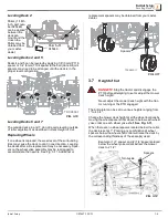
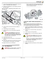
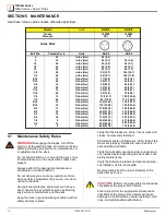
5.
Mount the Articulator
tow arm to the tractor
using the provided hex
head bolt, hex nut and
washers. See Fig. 3-4
NOTE:
Lastec
offers two optional 20” draw bars that can be used
to mount the tow arm to the tractor: 107667, Draw
Bar, 1 1/4” x 20” and 107670, Draw Bar, 1 1/2” x
20”107667, Draw Bar, 1 1/4” x 20”.
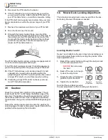
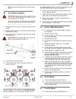
NOTICE
Ensure the distance limits do not exceed
the limits shown in Fig. 3-5 before installing the
shaft.
6.
Mount the PTO shaft to the Articulator, then to the trac-
tor.
NOTE:
Make sure the PTO shaft is in the correct
orientation.
7.
Secure the PTO guard retaining chains (located at
each end of the PTO shaft) to the Articulator pull bar
and the tractor.
These prevent the outer guard from turning with the PTO
shaft for safety purposes.
8.
Complete the entire Initial Setup section of this manual
before attempting to operate the Articulator
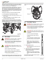
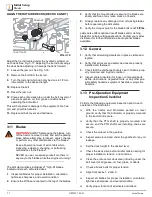
NOTICE
Allow a minimum 2” clearance between
the tractor tire and the Articulator tow arm.
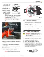
3.3 Hose Spring Installation
1.
Attach one of the provided tie wraps around the hoses
that are connected from the deck to the traction unit.
2.
Attach one of the provided tie wraps to an elevated
point on the traction unit.
3.
Assemble on end of the provided spring to the tie wrap
located on the traction unit.
4.
Assemble the opposite end of the hose spring to the tie
wrap locate around the hoses.
3.4 PTO Shaft Range Verification
CAUTION!
It is important to verify that the PTO
shaft falls within the proper operating range to
ensure safe operation of the Articulator under vary-
ing cutting conditions.
1.
Take the tractor and Articulator to your most severely
mounded area.
2.
Disconnect the PTO shaft from the tractor.
3.
Drive the tractor up a mound or across a ditch.
4.
Stop at the point where the tractor is headed up a
mound and the Articulator is headed down an opposing
mound, at the point where the PTO shaft will span the
valley of the two mounds with the tractor and Articula-
tor at their closest point. This should represent your
maximum PTO shaft compression.
SIDE VIEW
1-8x5 Hex
Head Bolt
Pivot Lock
Washer (2)
1” Split
Lock Washer
1-8 Hex Nut
FIG. 3-4
Max. 6”
Min 6” -
Max. 10”
End of Tractor
PTO
Output Shaft
PTO Shaft
Tow Arm
FIG. 3-5
721_081
FIG. 3-6
2" (50mm) Minimum


