background image

Laser Jailer Maintenance Manual 


00892-53-000 

Page 5 of 16


Issue 2          30 January 2020 


Installation 


3.1  Laser Jailer Tile Description 

 
The Laser Jailer tiles are made from a laminate material approximately 2mm thick. 
 
Each tile has a two 300mm long interconnection leads attached. A rear view is shown below showing 
the interconnecting leads and mounting spacers. 


Figure 1. Tile showing Rear View 


3.2  Laser Jailer Tile Fixing 

 
The  tiles  are  screwed  to  the  mounting  surface  with  M4  screws  and  20mm  tall  spacers,  the  gap 
behind being used for the interconnection leads between the tiles. 
 
The  tiles  should  always  be  screwed  into  place.  Adhesives  and  tapes  should  not  be  used  as  a  tile 
which  becomes  detached  may  fall  and  cause  injury.  For  small  enclosures  which  may  be  made  of 
sheet metal the spacers may be fitted directly into the enclosure wall. For larger enclosures where 
thicker  wall  material  is  used  the  tiles  are  often  supplied  in  groups  pre-assembled  to  larger  panels 
which may be screwed to the wall. 
 
When tiles are replaced it is usual to leave the spacers fitted to the structure. 


Summary of Contents for Laser Jailer

Page 1: ...Laser Jailer Maintenance Manual 00892 53 000 Issue 2 30 January 2020 LASERMET LASER JAILER ACTIVE LASER GUARDING SYSTEM INSTRUCTION MANUAL INSTALLATION MAINTENANCE AND REPAIR MANUAL Issue 2 ...

Page 2: ...ation 5 3 1 Laser Jailer Tile Description 5 3 2 Laser Jailer Tile Fixing 5 4 Wiring 6 5 Monitoring and Detection Circuit 8 5 1 General 8 5 2 Fault Latch 9 5 3 Real Time Fault Indications 11 6 Fault Location 12 6 1 Self Recovery 12 6 2 Equipment 12 6 3 Narrowing Down the Faulty Section 13 6 4 Identifying the Fault 13 6 5 Repair and Test 14 7 Warranty 15 8 Contact Details 16 ...

Page 3: ...chnicians should be aware that the Monitor and Detection board generates up to 36V with respect to earth which may be felt on contact The technician must ensure that any laser that may be connected to the interlock system is disabled so that it cannot be operated despite the interlock controller being armed Preferably this means isolating it from its power supply and ensuring that no one will reco...

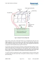
Page 4: ...s control of illuminated signage override facility door locking and so on The ICS is usually connected to the interlock connector on the laser or to a beam shutter so that the ICS can disable the laser beam if the enclosure is breached In the case of Laser Jailer if a powerful laser beam misses its target and hits a detection tile on the enclosure wall it is detected by the monitoring circuit whic...

Page 5: ...wed to the mounting surface with M4 screws and 20mm tall spacers the gap behind being used for the interconnection leads between the tiles The tiles should always be screwed into place Adhesives and tapes should not be used as a tile which becomes detached may fall and cause injury For small enclosures which may be made of sheet metal the spacers may be fitted directly into the enclosure wall For ...

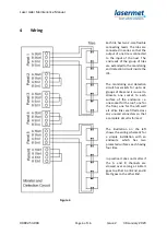
Page 6: ...as sockets for up to six groups of tiles and it is usual to allocate one socket to each surface of the enclosure i e one socket for the roof one for the floor one for the left wall etc Wire links are fitted across any unused connectors so that a complete circuit is formed The illustration on the left shows the wiring schematic for a simple installation with an enclosure which has two protected sur...

Page 7: ...atively be used for convenience For very large enclosures patch panels are sometimes used which allow large surfaces to be sub divided into smaller groups Such enclosures may contain a thousand or more tiles With so many tiles it may be hard to visually spot a damaged one so by dividing the surfaces into smaller groups of tiles it is easier to locate a damaged tile electrically Lasermet supply pat...

Page 8: ... circuits may be broken due to laser damage and this is also detected The same applies should a connection fail between tiles The circuit will also detect any electrical leakage to earth which might be caused for example if the insulation on a cable becomes damaged or if water ingress occurs Prior to arming the interlock controller the Monitor and Detection circuit is put into Test mode In this mo...

Page 9: ...he system to be repaired before it can be re used For example in some situations a user may attempt to electrically bypass a damaged tile in order to get the laser working again However this presents a hazard because a tile is now not monitored so part of the enclosure is not protected The fault latch keeps the interlock disabled if a tile is bypassed and unless configured otherwise even if the po...

Page 10: ...Laser Jailer Maintenance Manual 00892 53 000 Page 10 of 16 Issue 2 30 January 2020 Figure 6 Loop Open and Fault Latched indications ICS 5 and ICS 6 Figure 7 Loop Open Fault ICS 15 ...

Page 11: ...of the Fault latch as follows J8 J9 Enable Fault Latch The latch is disabled if the links are removed J10 J11 Auto Fault Reset If the links are fitted the latch can be reset by cycling the system power as described above If an external keyswitch or other control is provided to reset the latch it is connected in place of the jumpers on J10 and J11 and it should connect each pair of pins together mo...

Page 12: ...y be used to locate a fault in the tiles or interconnections Sometimes the damaged tile will be obvious Other times the damage might be difficult to see or there may be some other fault which is stopping the system from working A multimeter will be very useful Lasermet can also supply a handheld probe that can be used to locate faults A dummy tile can be made which is useful for substituting secti...

Page 13: ...al cable socket by socket until the faulty section has been identified The plugs may be inserted in any order for test purposes For example the cables for panel 2 may be inserted into the panel 3 socket etc 6 4 Identifying the Fault Once the faulty cable has been located the actual faulty part needs to be found Turn off the Interlock Controller With the cable unplugged from the Monitor and Detecti...

Page 14: ...tween one circuit and earth If the failed resistance test indicates a low value e g less than about 5kΩ and the reading is steady there could be an actual short circuit and its position can be predicted based on the theory that each tile adds 66 ohms to the resistance For example if the reading was 594Ω from the start one could predict that the fault is around the ninth tile from the start 594 66 ...

Page 15: ...fects in workmanship for 12 months Damage or defects caused by other factors are not covered For example industrial contamination incorrect cleaning storm damage Consequential loss is not covered under warranty Compensation for indirect or direct loss or damage is expressly excluded Rectification of the defects or a replacement does not initiate a new warranty period For all deliveries payments an...

Page 16: ...provide a complete system We also supply equipment and consultancy covering all aspects of laser safety Full support design and installation is available from Lasermet please contact us for any queries For sales and technical support Lasermet Ltd Lasermet House 137 Hankinson Road Bournemouth BH9 1HR United Kingdom Tel 44 0 1202 770740 Fax 44 0 1202 770730 Email sales lasermet com Website www laser...

Reviews: