Laser Jailer Maintenance Manual
00892-53-000
Page 8 of 16
Issue 2 30 January 2020
5
Monitoring and Detection Circuit
5.1 General
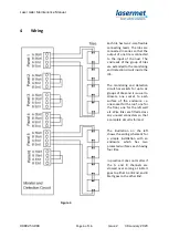
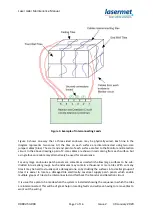
Each tile contains two separate circuits. Once all the tiles have been connected and the cabling
between them completed, two complete circuits are formed which pass through every tile. The
Monitoring and Detection circuit passes a test current through the two circuits.
When the system is in order the two circuits are both complete and there is a very high electrical
resistance between them.
If a laser damages a tile the resistance between the two circuits is reduced and this is detected and
triggers a shutdown of the laser.
Sometimes one or both circuits may be broken due to laser damage and this is also detected. The
same applies should a connection fail between tiles.
The circuit will also detect any electrical leakage to earth, which might be caused for example if the
insulation on a cable becomes damaged or if water ingress occurs.
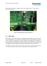
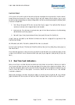
Prior to arming the interlock controller, the Monitor and Detection circuit is put into Test mode. In
this mode a simulated leakage fault is applied which should be detected by the circuit. If the
detector does not detect the simulated fault, the interlock controller will not arm. The picture below
shows the normal indications on the Monitor and Detection board before the system is armed. The
Leakage lights show that the simulated fault has been detected. This is not a genuine fault as the
Fault Latched light is not lit.
Figure 4. Normal Indications prior to arming Interlock Controller

