background image

Safety Information

Operating Safety

Prior to use

To reduce the risk of personal injury, ensure the 

surrounding area is in good order and free of 

debris.
 To reduce the risk of shifting, rolling, or 

overturning, locate the light tower on a firm, level 

surface, with enough space to deploy the trailer’s 

outriggers.
Do not allow water to accumulate around the base 

of the light tower.

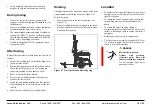
To improve stability, deploy the outriggers prior to 

raising the light tower mast.
The light tower mast can be extended to 24.6 feet 

(7.5  meters) in height. Ensure the area above the 
trailer is clear of obstructions.

Ensure the light tower is in good operating condition:

Check tires, lights, protective lamp covers, 

electrical wiring, and the engine for obvious signs 

of wear or damage.
Never use any equipment that is damaged or in 

need of repair.

During operation

-Ensure the trailer is well grounded, per all

applicable regulations.

-Never raise, lower, or move the trailer while the

light tower is in use.

-Do not collapse the outriggers or move the trailer

while the light tower mast is vertical extended.

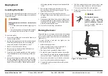
-When not in use, or in case of high winds, lower the

light tower mast to the travel position (see page

14).

-Light bulbs can be extremely hot. Always allow

bulbs to cool at least 15 minutes before handling.

WARNING

Improper use of equipment

could cause serious injury or

death.

Prior to using this product,

carefully read, understand, and

observe all instructions in this

manual and the engine manual.

CAUTION

Crush hazard.

When operating or working on

the light tower, keep hands and

body parts clear of pinch

points.

DANGER

Electric shock hazard.
Contact with overhead

electrical power lines will

cause serious injury or death.

Do not position light tower

under power lines.

WARNING

Falling equipment could cause serious injury

or death.

When raising or lowering the light tower 

mast, ensure the area directly behind the 

trailer is clear of people.
If the mast “hangs up” or the winch cable 

develops slack while raising or lowering the 

mast, stop immediately, move away from the 

unit and contact Atlas Copco.

Larson Electronics, LLC


  Phone: (800) 369-6671 

 Fax: (903) 498-3364 

  www.larsonelectronics.com 

4

 of 

33


Summary of Contents for WCDE-6-NL

Page 1: ...WCDE 6 NL Mobile Light Tower 6kW Diesel Generator 30 Tower 30 Gal Capacity w 60 hr Runtime NO LAMPS Manual...

Page 2: ...3 Light fixture wiring 12 4 Operation 13 4 1 Safety 13 4 2 Control panels 13 4 2 1 Towing and hoisting 13 4 2 2 Before towing 13 4 2 3 During towing 14 4 2 4 After towing 14 4 2 5 Hoisting 14 4 3 Loca...

Page 3: ...des an undercarriage frame axle and towbar The light tower is very useful for construction sites where neither electricity nor lighting is available Larson Electronics LLC Phone 800 369 6671 Fax 903 4...

Page 4: ...collapse the outriggers or move the trailer while the light tower mast is vertical extended When not in use or in case of high winds lower the light tower mast to the travel position see page 14 Ligh...

Page 5: ...soline other fuels or flammable solvents to clean parts DANGER Asphyxiation hazard Operate the engine outdoors and keep away from engine exhaust If operating in an enclosed area vent exhaust fumes to...

Page 6: ...oose clothing away from moving parts on engine and generator Keep the light tower and all its components clean Keep labels legible Replace damaged or missing labels Replacement labels are available fr...

Page 7: ...olts that hold the tow hitch to the draw bar 2 Lift the hitch off the drawbar and rotate the hitch end to end 3 Return the hitch to the draw bar making sure to align the bolt holes 4 Reinstall the bol...

Page 8: ...Light fixture wiring LAMPS NOT INCLUDED WITH UNIT Larson Electronics LLC Phone 800 369 6671 Fax 903 498 3364 www larsonelectronics com 8 of 33...

Page 9: ...If necessary attach a red flag to the top of the mast 2 Check tires wheels and lights a Check tires for wear Replace worn tires b Verify tires are fully inflated to the proper pressure c Verify that...

Page 10: ...off the tow vehicle 6 Move the tow vehicle away from the trailer Hoisting The light tower may be hoisted by means of the hoist ring mounted on the lifting beam see Figure 3 2 Prior to hoisting Ensure...

Page 11: ...er with the remaining three jacks 10 Use leveler for leveling the machine Raising the tower When the tower is vertical the mast can be extended to 24 5 feet 7 5 meters The tower can be rotated 360 deg...

Page 12: ...ls are blocked or chocked 3 Level the trailer and extend the outriggers 4 Connect the trailer ground stud to earth ground 5 Take the weather into account do not raise or use the tower in high winds or...

Page 13: ...ast a Loosen the rotation lock knob b Use the handle on the mast to rotate the mast until the mast mounted winch is on the same side of the mast as the trailer tow hitch c Tighten the rotation lock kn...

Page 14: ...r light goes out turn and hold the key at the START position 4 Release the key as soon as the engine starts or after 10 seconds if the engine does not start Figure 3 7 Key slot and glow plug indicator...

Page 15: ...p life turn off lights and let the lamps cool 15 minutes before lowering the tower and moving the trailer After the lamps are turned off they will not turn on again until they are cool The lamps can t...

Page 16: ...of the lamp stabilizer Once removed swing the stabilizer to the side and unscrew the lamp 2 To install a lamp IMPORTANT Lamps will last longer if they are free of contaminants To protect a new lamp fr...

Page 17: ...s will cause severe injury or death Turn off power before servicing any component on the light tower Only a qualified electrician should service the light tower electrical system Larson Electronics LL...

Page 18: ...fuel level 3 X Check air intake vacuum indicators X Check for leaks in engine air oil or fuel system X X Check function of coolant heater option X Check on abnormal noise X Check electrical system cab...

Page 19: ...1000 hrs Check Test glow plugs grid heater X Check rubber flexibles 7 Check emergency stop X Clean radiator 1 Replace air filter element 1 X Check Replace safety cartridge X Inspection by Atlas Copco...

Page 20: ...Figure 4 4 Comprehensive wiring schematic 9829 3800 74 Larson Electronics LLC Phone 800 369 6671 Fax 903 498 3364 www larsonelectronics com 20 of 33...

Page 21: ...ls 4 Capacitor 5 Generator terminal block 6 Control box lights Wire Colours B Black Br Brown Cl Clear G Green Gr Grey L Blue LL Light Blue Or Orange P Pink Pr Purple R Red Sh Shield T Tan V Violet W W...

Page 22: ...d tail lights c Side light amber d Side light red e License plate light Wire Colours G Green Right stop and turn lights Y Yellow Left stop and turn lights Br Brown License plate tail and side lights W...

Page 23: ...Figure 4 6 9829380078 Larson Electronics LLC Phone 800 369 6671 Fax 903 498 3364 www larsonelectronics com 23 of 33...

Page 24: ...355 5939 2 233 828 3093 121 772 406 15 984 2965 1 116 735 1887 74 291 990 4 38 994 Cooling Air Inlet Cooling Air Outlet Lifting eye 50 Frame Drain Larson Electronics LLC Phone 800 369 6671 Fax 903 49...

Page 25: ...13 484 342 5 13 484 1577 5 62 107 1349 53 111 700 27 559 920 36 220 Service Door For cleaning cooler Exhaust Air outlet Emergency Stop Larson Electronics LLC Phone 800 369 6671 Fax 903 498 3364 www l...

Page 26: ...ng tires whether we can feel the obvious gap Re adjust the axle hub bearing axial clearance Steps Remove the wheels and wheel covers Remove the slotted nut cotter pin Tighten shaft nut then back to lo...

Page 27: ...is also used for floodlight operation switch on the floodlights manually S20 ON switch on off the floodlights automatically in REMOTE mode S20 REMOTE 3 START Is used to start the unit in Manual mode I...

Page 28: ...n Engine speed instrumentation screen Hours run instrumentation screen Battery voltage instrumentation screen Oil pressure instrumentation screen Coolant temperature instrumentation screen Fuel sender...

Page 29: ...st and the unit is waiting for a manual start Appears when a timer is active for example cranking time crank rest etc Appears when the engine is running and all timers have expired either on or off lo...

Page 30: ...e desired event 4 Continuing to press the UP or DOWN buttons will cycle through the past alarms 5 To exit the event log press the UP and DOWN buttons simultaneously Setting the Lc1003 clock and timer...

Page 31: ...00 00 905 Scheduler 1 Start Day 0 1 Monday 906 Scheduler 1 Start Week 1 2 3 4 907 Scheduler 1 Duration 0 00 00 908 Scheduler 2 Start Time 0 00 00 935 Scheduler 8 Duration 0 00 00 Configuration Parame...

Page 32: ...heduler ON 902 Schedule run On or Off load ON 3 To program the settings for Event 1 proceed as follows 903 Schedule period 0 Weekly Event 1 repeats every week 1 Monthly Event 1 repeats every month Sug...

Page 33: ...nge that falls below the set sensitivity level Remote start will be triggered and the floodlights of the light tower will switch on automatically if Remote start and Auto mode are selected see also ch...

Reviews: