
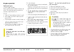


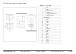


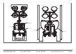


Figure 4.5 Generator-capacitor excitation schematic
Reference
Description
1
Rotor
2
Stator
3
Excitation coils
4
Capacitor
5
Generator/terminal block
6
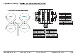
Control box lights
Wire Colours
B
Black
Br
Brown
Cl
Clear
G
Green
Gr
Grey
L
Blue
LL
Light Blue
Or
Orange
P
Pink
Pr
Purple
R
Red
Sh
Shield
T
Tan
V
Violet
W
White
Y
Yellow
Larson Electronics, LLC
Phone: (800) 369-6671
Fax: (903) 498-3364
www.larsonelectronics.com
21
of
33


