


2
Larson Electronics LLC - 1.800.369.6671 - [email protected] - larsonelectronics.com
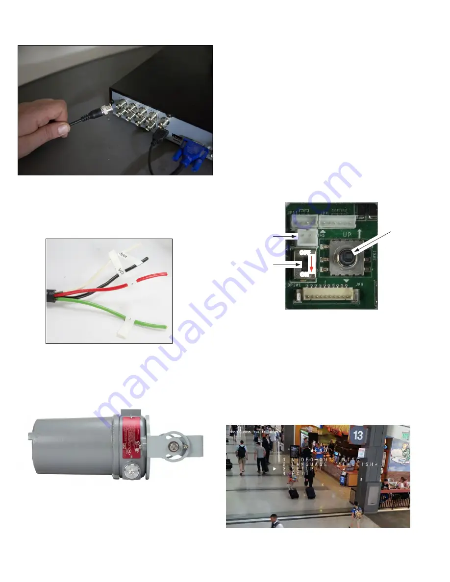
Plug into you DVR
Camera adjustments
1.
Apply power to the camera.
2.
Verify that video from the camera can be seen on a monitor. NOTE:
Video from the CVBS drop able or the video test cable is NTSC video
and can be displayed on most NTSC compatible monitors. Video from
the HD-TVI drop cable must be connected to an HD-TVI compatible
video recorder (DVR) system.
3.
While observing video from the camera, loosen the mounting bracket
pan, elevation and horizontal line adjustment lock screws, point the
camera at your surveillance target, and then tighten adjustment lock
screws or nuts to hold the camera in position.
USING THE OSD
Use the OSD to adjust the internal settings of the camera to customize it for
the installation venue.
1. Unscrew the lens cover of the camera to access OSD joystick and WDR
switch. See photos above.
For power hookups connect DC positive to the wire labeled (+) and DC
negative to the wire labeled (-) using terminal strips.
Plug for
video test
cable
WDR
OFF/ON
switch
NOTE:
If WDR switch is
ON, CVBS output is
disabled. The OSD
WDR setting overrides
the switch
p
OFF
t
u
ON
q
OSD
joystick
24V DC power source. See Specifications for wattage requirement.
The OSD joystick is used to open the OSD menu and navigate through the
menus. To open the camera menus and select a menu option, press the joystick
down (in toward the camera body). To navigate the menus, rock the joystick up
(UP (p), see photo above) or down (q) to move through the parameter list menus
vertically, rock the joystick left (t) or right (u) to change the parameter value that
appears for the parameter. Press the joystick down (in toward the camera body)
to select the parameter value shown. Changes made to the OSD setup must be
saved to be restored after power off and power on.
Most menus have a RETURN that returns you to the previous menu. EXIT closes
the OSD.
2. Open the OSD menus by pressing the joystick in toward the base
assembly. The OSD menu tree is shown below. Use the OSD to configure
the camera as needed.
OSD top level menu


