


PULSE MODULATED ACTIVE INFRA-RED BEAM
FOR HAZARDOUS AREAS ZONE 1 OR ZONE 2
The GS100 IR beam set carries ATEX certification for use within the
petrochemical industry, or other similar industries where an explosion-proof,
flameproof, weather, or dust proof housing is required.
The electronic modules and associated housings have been designed &
assembled in accordance with ATEX DIRECTIVE 2014/34/EU.
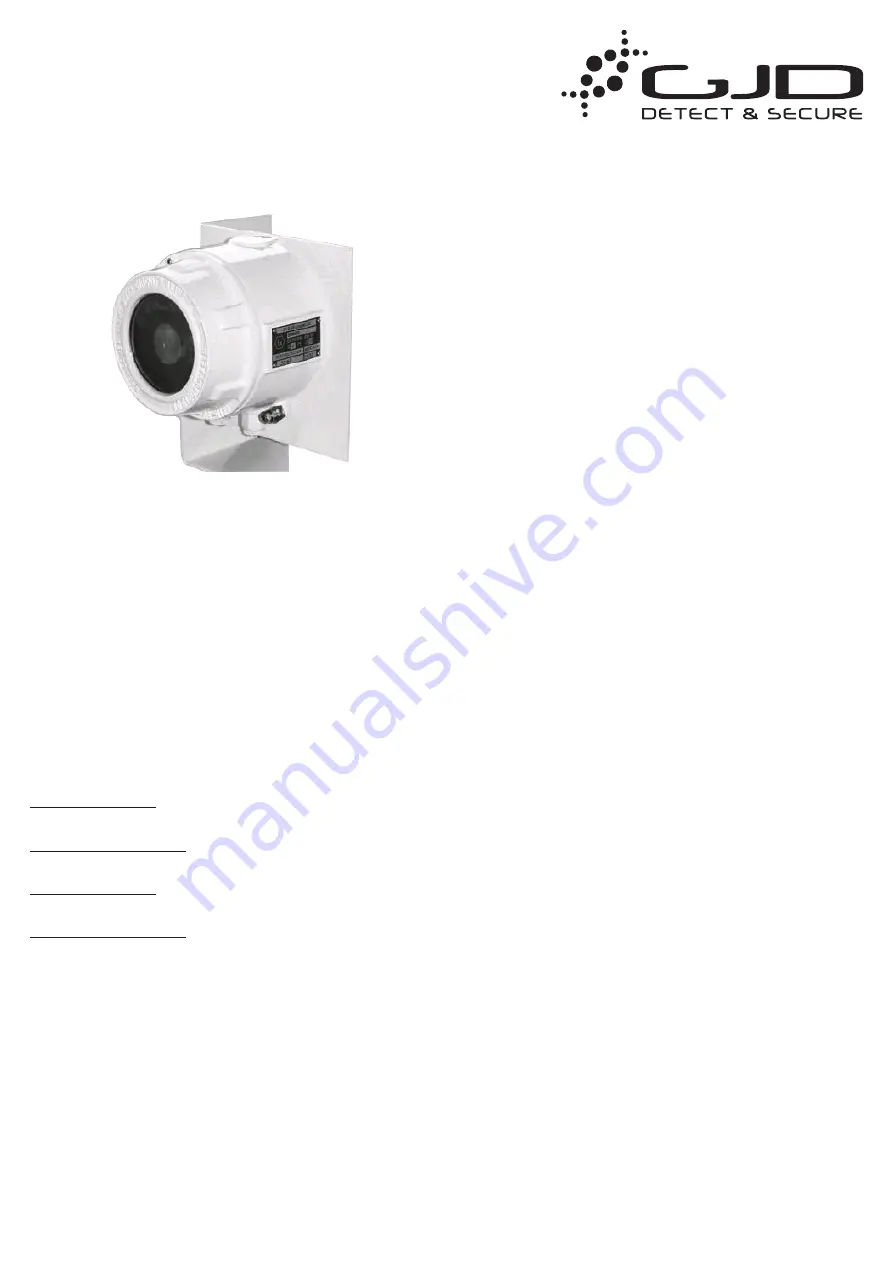
Product Description
Flameproof IR Transmitter & IR
Receiver Enclosure
II 2 G Ex d op is IIC T6 Gb -20 °C ≤ Ta ≤
+40 °C, IP66
II 2 D Ex tb op is IIIC T80°C Db IP66
Type
EMH29
CERTIFICATION AND CONFORMITY
EN 60079-0:2012/A11:2013, EN 60079-1:2014, EN 60079-31:2014,
EN62368-1:2014
Suitable for:
European Classification
Group II Category 2 G Zone 1 & Zone 2 Hazardous areas
North American Classification
Class I, Division 1 & Class I, Division 2
European Classification
Group II Category 2 D Zone 21 & Zone 22 Hazardous areas
North American Classification
Class II, Division 1 & Class II, Division 2
In accordance with EC type examination certificate No. TRAC13ATEX0054X,
a review of EN 60079-0:2012/A11:2013, EN 60079-1:2014, EN 60079
31:2014 and Manufacturing Specification and Parts List-06109 EMH29-
06108.
This product is a component system and is intended for inclusion within
other equipment fitted by professional installers only.
The unit must not be operated as stand alone equipment.
Where applicable, compliance with the EMC directive or Machinery Directive
is the responsibility of the installer.
GS100-ATEX
Hazardous Areas Infra-Red Beam
GENERAL
The GS100 beam set is a detection device only, and is designed to be used
in association with alarm annunciation equipment, or other devices that
provide a means of monitoring the GS100 voltage free relay alarm output
(i.e. CCTV / NVR integrations, etc).
The beam set comprises of two parts, an infra-red beam transmitter, and
an infra-red beam receiver. Both modules are mounted within a flameproof
(EExd) enclosure c/w gasket, chromate primed and polyester coated white
finish.
A heat strengthened plate glass aperture is incorporated in which the
infra-red beam is projected (via TX optics) and monitored (via RX optics). An
interruption in the ‘aligned’ beams path, is designed to provide a change of
relay state at the receiver (N/C & N/O alarm relay O/P).
A heater element can optionally be provided in both the transmitter (TX) and
the receiver (RX), to help combat the build up of condensation.
It is however normal practice to fit such a device to the RX housing only,
as an attempt to tamper with the TX device will automatically generate an
output at its associated receiver. i.e. if the TX optics are moved, supply
interrupted, or device is low in voltage, the low energy projected infra-red
beam, or no projected beam present, will be detected by its associated
receiver.
As the beam sets use an infra-red light source that is invisible to the human
naked eye, a beam alignment voltage output is provided for this process, via
a terminal (align. O/P), or test pin.
Additionally, an optical alignment module is provided, that may be used
(placed on) the TX and RX optical assemblies to aid initial alignment, prior to
final alignment via the voltage O/P.
The voltage O/P is designed to be used with a standard voltmeter
(0 – 10VDC), or for easy single man alignment operation, via an optional
‘Mini-strobe’ beam alignment tool.
The GS100 incorporates both high security ‘Asynchronous’, and
‘Synchronous’ beam set synchronisation, allowing many sets of beams to
be installed on the same site, or indeed stacked above each other (greater
detection), without ‘cross interference’.
The use of the synchronisation facility when installing only one set, or
several sets in different locations of a site is recommended (although not
essential). Doing so will ensure that the receiver (RX) circuitry ignores other
infra-red light sources that may unknowingly be present and falling directly
on the RX optical axis (invisible to see).
Synchronisation monitoring is incorporated when the interconnections are
made, refer to technical specification.
It is recommended that the 12VDC supply have a floating output to accept
the negative earth, and that all cables should be screened throughout their
entirety.


