


phone +49 351 871-8615
fax
+49
351
871-8727
e-mail [email protected]
www.InfraTec.net
InfraTec GmbH
Infrarotsensorik und Messtechnik
Gostritzer Straße 61 63
01217 Dresden/GERMANY
international
phone fax
InfraTec Ltd. - United Kingdom
+44 1246 267560
+44 1246 267561
InfraTec S.A.R.L. - France
+33 1 60 53 56 06
+33 1 60 53 56 09
InfraTec Sp. z o.o. - Polska +48 71 372 15 32
+48 71 327 98 59
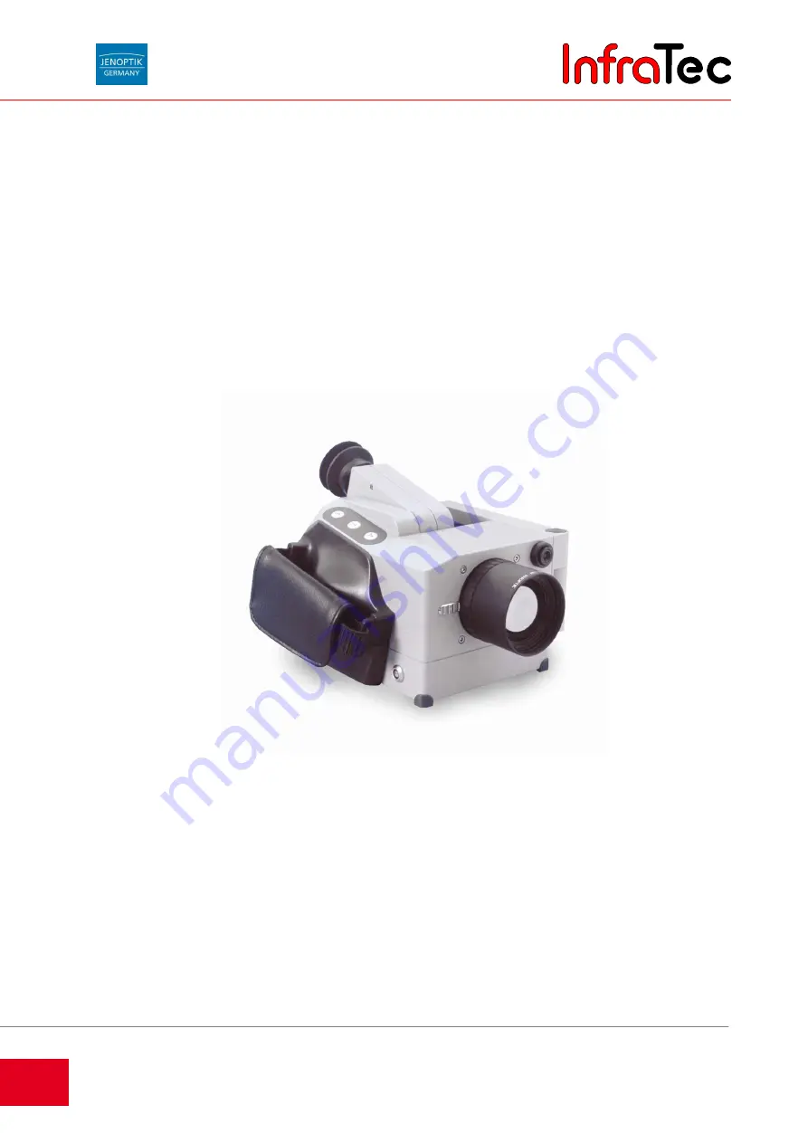
VarioCAM
®
incl. IRBIS
®
remote software description
incl. IRBIS
®
software description
Operating Instructions
State: February 28, 2007
InfraTec
Summary of Contents for InfraTec
Page 2: ...I n f r a T e c ...


