
EPS-2XPB-SG-AT-V3
Larson Electronics, LLC
Phone: (800) 369-6671
Fax: (903) 498-3364
www.larsonelectronics.com
2
of
3
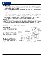
INSTALLATION
1.
Mount the back box by means of mounting lugs. Install conduit nipple and sealing fittings, to be installed on each
conduit
entrance or exit to the enclosure back box in Class I and Class II areas. Thread conduit into sealing fitting
(Note: For Class I
areas, the conduit should engage [5] full threads.)
2.
The conduit threads should be lubricated with a non-electrical insulating lubricant or pipe joint compound that will
not promote
corrosion or chemically attack aluminum.
3.
After conduit system has been properly installed, pull the wires and make electrical connections as required. The
electrical
circuits and ground continuity should be checked with an instrument approved for the area. Notice:
Connect only copper wire to
this device.
4.
All conduits entering or leaving the enclosure must be sealed within 18” of the enclosure with listed sealing
fittings. Caution
must be taken during installation to be sure that the ground flange flame joints of the cover and
box are not scratched, nicked,
or damaged. Before assembly of the cover to the box, the mating ground surfaces
of both the box and cover should be wiped
clean to assure that the ground flame joint will be free of all foreign
particles such as lint, dust or dirt.
5.
After tightly bolting the cover assembly/assemblies to the enclosure, all box to cover flame joints should be
checked with a
0.0015” thick feeler gauge such that the gauge will not enter the flame path more than 1/8” at any
point.
MAINTENANCE
All moving shafts should be lubricated
occasionally to prevent binding. Only use a
lubricant which is suitable for use with
aluminum or stainless steel. If devices are
to be installed in corrosive areas which will
attack aluminum alloys containing less than
0.4% copper (boxes and covers) and 303
stainless steel (mostly shafts), the device
should be suitably protected from the
corrosive material.
CAUTION:
To prevent ignition of
hazardous atmospheres, disconnect from
the supply circuits before opening the
enclosure; keep tightly closed while circuits
are energized.
OPERATION
The EPS-2XPB-SG-AT-V3 offers adjusted timing control of motors in hazardous locations. This explosion proof switch is designed to
operate with 100-240V AC/DC 50/60 Hz and comes with a 10-amp rating (at 600V AC). The unit requires sealing fittings and compound
within 18 inches of conduit entrances. A solid-state, encapsulated time delay relay can be found inside the switch, which offers an
adjustable timer range of 10 seconds to 170 minutes. When the button is engaged, the circuit stays closed, keeping the connected motor
or device running for the set duration (between 10 seconds - 170 minutes in 1 second increments). The timer component features a
repeating accuracy value of +/- 0.5% and a setting accuracy value of +/- 2%. Controls for the explosion proof timer includes: (1) green
push button - start timer and (1) red push button - stop timer early before set time.


