background image

21

NOVA MIX 2K

English

H7

H7

H4

H

WASHING

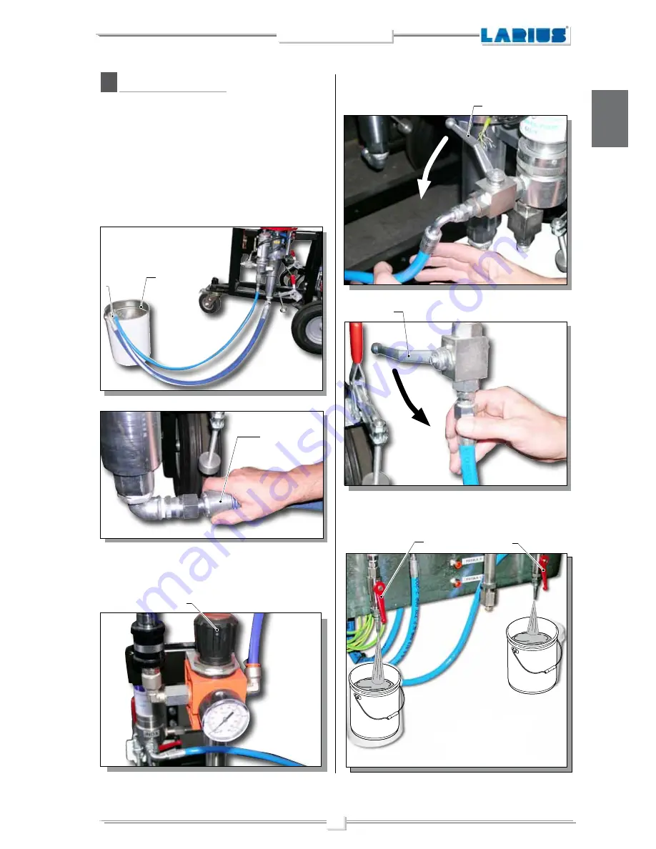
Empty any product present inside the machine. 
For example, after complete washing (the machine has sucked 
up solvent).

• Remove the floaters (

H1

) from the drums (

H2

) or unscrew and 

detach the supply tube (

H3

) from the pumps, to be sure that the 

pumps can no longer suck up the products.

H2

H1

• Set the pressure of the pumps (

H4

) to the minimum for them to 

work, using the regulators on the pumps themselves.

• Leave the delivery valves open (

H5

) and open the recirculation 

valves as well (

H6

).

H5

H6

• Open the two relief valves located under the digital pressure 

gauges (

H7

).

H3

MAINTENANCE

Summary of Contents for NOVA MIX 2K

Page 1: ...For 2 component applications Certified stainless steel pump Atex II 2G c IIB T6 ENGLISH OPERATING AND MAINTENANCE INSTRUCTION OPERATING AND MAINTENANCE INSTRUCTION PAINT SPRAYING EQUIPMENT Ed 010 11 11 ...

Page 2: ... manual without prior notice This manual is to be considered as an English language translation of the original manual in Italian The manufacturer shall bear no responsibility for any damages or inconveniences that may arise due to the incorrect translation of the instructions contained within the original manual in Italian ...

Page 3: ...ENT p 5 TRANSPORT AND UNPACKING p 9 SAFETY RULES p 10 Conditions of guarantee p 11 SETTING UP p 11 Product pump connection p 12 Check on power supply p 14 Connecting the equipment to the pneumatic line p 15 Washing of the new equipment p 16 Preparing the product p 16 WORKING p 17 Starting uo and charging the machine p 17 Procedure for checking component dosage p 19 Flow p 20 MAINTENANCE p 21 Washi...

Page 4: ...of the gun or from possible leaks may cause injections into the body To prevent the risks of fire or injection Use the safety lock of the gun trigger when you are not spraying Do not place your hands or fingers on the gun nozzle Do not attempt to stop leaks with your hands body or anything else Do not aim the gun at yourself or anyone else Do not spray without the special nozzle protection Release...

Page 5: ...d the mixing of the components are regulated by an electronic control system The hydraulic unit contains two flowmeters which regulate the input of the two components into the mixing lines It is here thanks to a static mixer that the mixing of the products takes place The machine is made up of 4 main units The pump for the components unit The hydraulic mixing unit The command and control unit Equi...

Page 6: ...esthefluidityofthepaintwithout the use of solvents increase the thickness of the protective film and improves the finishing Bi component water soluble paints bi component solvent paints Min 1 1 Max 30 1 decimals included Max 14 lt min 400 bar 1 7 bar 230 V 50 Hz min 5 C max 50 C 74 dB 320 Kg 1000 mm 1300 mm 1480 mm Based on the characteristics of the paint to be used the air pressure supply and th...

Page 7: ...tic unit 3 A B components tanks 4 Visual alarm device located on the control panel 5 Power supply panel electric pneumatic version 6 Electric generator for pneumatic only version POS DESCRIPTION DESCRIPTION OFTHE EQUIPMENT ANTIFREEZE SYSTEM 6 1 4 5 2 3 1 4 5 6 ...

Page 8: ...6 NOVA MIX 2K English 7 Mixing head 8 Pressure digital viewer 9 Air filter regulator 10 Air distribution collectors POS DESCRIPTION 8 10 7 9 10 8 7 9 ...

Page 9: ...Auxiliary air distribution group 12 Air regulators for pump supply 13 Eye bolts for lifting Note Do not use the eye bolts of the pumps to lift the machine 14 Product filter POS DESCRIPTION 13 13 13 12 12 14 11 14 13 12 13 11 13 ...

Page 10: ...e 16 Washing pump 17 Air accumulation lung for electro pneumatic group 18 Component heater A B 19 Encoder for dosage of components A B 20 Component pump A 21 Component pump B 22 Comand box POS DESCRIPTION 22 18 17 15 19 21 15 17 18 20 16 ...

Page 11: ...of the machine s fragile elements which could be damaged from the tension produced during lifting All of the operations described in this paragraph must be performed by qualified technicians who have been trained for the task required Before lifting and moving the machine make sure that the equipment being utilised is of an adequate size to bear the weight of the machine and its components Do not ...

Page 12: ...KEEP PROPER BALANCE AVOIDING UNUSUAL STANCE BEFORE USING THE TOOL ENSURE THERE ARE NOT DAMAGED PARTS ANDTHE MACHINE CANWORK PRO PERLY ALWAYS FOLLOWTHE INSTRUCTIONS ABOUT SAFETY AND THE REGULATIONS IN FORCE KEEP THOSE WHO ARE NOT RESPONSIBLE FOR THE EQUIPMENT OUT OF THE WORK AREA NEVER EXCEED THE MAXIMUM WORKING PRESSURE INDICATED NEVER POINTTHE SPRAY GUN ATYOURSELVES OR AT OTHERPEOPLE THECONTACTWI...

Page 13: ...TILISED IFNECESSARY USEWARNINGSIGNSTOKEEPANYONE PRESENT AT A SAFE DISTANCE MAKESURETHATTHEREISALWAYSSOMEONEWITHIN SHOUTING DISTANCE IN CASE AN ACCIDENT SHOULD OCCUR SETTING UP The machine is equipped with an anti freeze system that allows it to work even at very low temperatures However after a few minutes of operation the upper metal outer surface cools dramatically Avoid touching the area indica...

Page 14: ...1 to the pump F2 and the tank F3 or to your product container F4 B Recirculation Connect the flexible recirculation tube F5 between the pump F6 and the upper part of the tank F7 or to your product container F4 NOTE The procedures A and B must be carried out on both the pumps and tanks F7 F5 F6 F5 F3 F1 F2 F4 F4 ...

Page 15: ...the pump of component B and the related mixing group A and B F8 D Washing connection Connect the suction tube F11 to the pump F13 Connect the recirculation tube F9 to the pump F13 Immerse the two tubes F11 F9 into the container F12 of washing liquid Connect the delivery hose F14 to the mixing group F10 for washing F10 F11 F9 F12 F13 F14 F8 ...

Page 16: ...It is recommended to use the tubes which have been supplied along with the machine NEVER use a damaged or repaired flexible tube The machine requires a 220V alternating current power supply LARIUS NOVA MIX 2K equipment is fitted with an additional external earth cable that is connected to the stem on the pump unit be means of a specific clamp F20 in order to protect the operator against any risk o...

Page 17: ...rth socket in any way ONLY use electrical connections that are earthed Make sure that any earth extension cords are in good condition ONLY use three core extension cables Avoid direct contact with the rain Keep the equipment in a dry place The machine must be connected to the compressed air feeding system which is necessary for the pneumatic interlocking The connection must be carried out in the f...

Page 18: ...use of that please contact the supplier of the product Never use products containing halogen hydrocarbons as methylene chloride If these products come into contact with aluminium parts of the equipment can provoke dangerous chemical reactions with risk of explosion In order to prepare the products i e for dilution refer to the supplier s data sheets Absolutely avoid to spray solvents indoors For d...

Page 19: ... the side switch G4 located on the control panel in position I 3 Power the pumps with compressed air and set the two regu lators to minimum G5 and G6 4 Open the recirculation valves G7 and G8 allowing the product to begin recirculation NOTE If you are not sure that the first part of the product is properly cleaned discharge the first part which starts to recirculate outside the tanks to avoid cont...

Page 20: ...llows for the elimination of any eventual air bubbles within the circuit 8 Close the manual discharge valves G11 9 Bring the pumps to the desired pressure and begin working G12 Wait for the flexible spray gun tube to load wait for the valves G11 to shut off automatically Before painting spray the product into a container G16 or into a part of the cab G17 dedicated to purging while keeping the spra...

Page 21: ...lowing procedure in order to check the quantities of the two components just before they are mixed Mount the component tapping blocks G18 Open the valves G19 and set the tapping cycle in order to check the dosage of the components The machine must not be pressurized By positioning the 2 containers G20 in correspondence to the 2 outlets the operator can check the actual amounts dispensed by the mac...

Page 22: ...2 pumps NOVA send the components to the NOVA MIX 2K machine In the NOVA MIX the components flow through the pressure gauge and the mixing group The components then enter their respective nozzles located on the mixing block Based on the settings provided by the machine theseregulatethepassageofthematerialsinorder to obtain a proper mixture Along the length of the block and of the mixing tube the 2 ...

Page 23: ...unscrew and detach the supply tube H3 from the pumps to be sure that the pumps can no longer suck up the products H2 H1 Set the pressure of the pumps H4 to the minimum for them to work using the regulators on the pumps themselves Leave the delivery valves open H5 and open the recirculation valves as well H6 H5 H6 Open the two relief valves located under the digital pressure gauges H7 H3 MAINTENANC...

Page 24: ...ve H10 located at the machine inlet open the 3 recirculation valves H11 Pump A and B washing H11 H12 H12 Open the two relief valves located under the 2 digital pressure gauges H12 manually open the three solenoid valves Ev A Ev B Ev L and spray in such a way as to ensure that the residual pressure is released discharge and reset all the regulators H13 present on the machine make sure that the pres...

Page 25: ...valve H14 of the pump you want to inspect to cut the air supply and discharge the pressure if it is a Nova pump close the delivery valve H15 H16 Slowly open the recirculation valve H16 Wait for the filter tank to empty H17 Open the filter tank to inspect it as indicated below unscrew the filter H18 using a suitable spanner H19 H20 remove the cover H20 ...

Page 26: ...ersists loss of product to replace the seals Crown oil filler Cup grease port Key Ref 11504 Always close the compressed air supply and discharge the pressure in the system before inspecting or carrying out any maintenance work on the pump H21 unscrew the filter H21 with the spanner H22 H22 H23 remove the filter H23 and proceed to cleaning with the wa shing liquid GASKET PACK REGULATION When necess...

Page 27: ...ssure inside the mixing block Open and close the three valves on the mixing block a few times see the page regarding manual controls in the manual ROUTINE MAINTENANCE Remember to perform a wash cycle before any lengthy periods of disuse Periods of disuse can be judged according to the POT LIFE of the components which are being utilised The manufacturer recommends for a wash cycle to be performed a...

Page 28: ... in function selecting the desired function in manual mode CONTROL PANEL The Control panel I1 is used in conjunction with the Operating Panel by the user to control machine function to select the cycles manual automatic andfunctionalities aswellasforimmediately viewing the system s functional status The light on the panel indicates whether any alarms are active ALARM CHECKS The PLC reacts in the f...

Page 29: ...ual cycle keeps most of the interlocking parts disabled It is therefore the operator who must activate or deactivate each single function Theoperatorwillberesponsibleforthecorrectuse the system s functions in order to avoid damaging or blocking the lines During automatic function the selection of the manual cycle will provoke the arrest of all of the system s functions and the cancellation of the ...

Page 30: ...and set the value to 1 The valve will open automatically The valves are defined as follows Ev L wash electrovalve manual control Ev A component A electrovalve manual control Ev B component B electrovalve manual control These three fields can be used to switch over open every single electrovalve while the selector J1 is set to Manual Modify the field s value to 0 or 1 in order to activate or deacti...

Page 31: ...anual position When the automatic cycle is active the program controls the sequence of the valves for the two components and doses them based on the requested ratio and based on the impulse count frequency settings JustpresstheF1buttontoaccessthe GeneralSettings screen The adjustment of the impulse count frequency must be done in such a way so as to avoid high frequencies which may not be supporte...

Page 32: ...arms during the work cycle OP73 scren Description of the function buttons Button General settings Impulse count frequency A B ratio Impulses to count A Count actual A Impulse to count B Actual count B Current impulse frequency Current A B ratio Current Pot life min PAGE 1 Button Wash T1 000 Manuals Ev L Ev A Ev B PAGE 1 Button Control settings Pof life min ratio error Ratio control cycle number Mi...

Page 33: ...may damage the electrovalves This number must be set in accordance with the viscosity of the materials as well as the pressure with which the machine is working High pressure low viscosity and a low IMPULSE FREQUENCY may cause excessive stress to the equipment and lead to non homogeneous mixtures Impulses to count A 000 Actual count A 000 Impulses to count B 000 Actual count B 000 A B RATIO The vo...

Page 34: ...enever work has been completed and the machine is not expected to be used for a number of hours This down time can be judged based on the pot life of the components being used i e at the end of the working day or before lengthy pauses If one or both of the components is changed perform a complete washing cycle in the entire LARIUS NOVA MIX 2K system starting from the flow pumps The wash fluid must...

Page 35: ... cycle cannot be initiated from the control panel the valve will have to be switched manually using a flathead screwdriver Alternate valve opening between the wash fluid and the air thereby simulating an automatic wash cycle ENABLING CONTROL CYCLES AND SPECIFYING THE NUM BER OF CONTROL CYCLES Only for machines which are properly equipped for verifying component dosage These two fields allow the us...

Page 36: ...to select YES or NO Press the button to reset the values Press the F3 button to set the panel s menu language ALARMS Notice text Text Notice Text ALARMS Air pressure missing alarm ALARMS SCREEN System in emergency status alarm indicates that the mu shroom emergency push button on the control panel has been pressed Reset reset the emergency button and press F4 Remove text takes place automatically ...

Page 37: ...expired Reset perform a wash cycle or spray and press F4 Remove text takes place automatically by pressing F4 Component A pressure alarm indicates that the pressure of component A is not within the proper range Reset check the pressure and pump circuit and press F4 Remove text takes place automatically by pressing F4 Component B pressure alarm indicates that the pressure of component B is not with...

Page 38: ...the led flashes replace or repair the valve Remove text turn the selector to its manual position turn it back to automatic and then press F4 AUTOMATIC CYCLE When the automatic cycle is active the program controls the sequence of the valves for the two components and doses them based on the requested ratio and based on the impulse count frequency settings Press the F1 button to access the General S...

Page 39: ...PAINT SPRAYING EQUIPMENT L innovazione Quella vera ...

Page 40: ...Rif 24477 pag 53 AB Air supply tank Rif 24479 pag 55 AE Encoder kit for compo nent dosage Rif 24488 pag 58 AG Heater with A component Ref 24493 page 60 Heater with B component Ref 23494 page 61 AH AF Flowmeter kit for Ghibli mix comp dosage Rif 24489 pag 59 AI Wheels Rif 24496 pag 62 O W Machinesteeringgearassembly Ref 24417 page 50 OPERATING AND MAINTENANCE INSTRUCTION OPERATING AND MAINTENANCE I...

Page 41: ...ntrol box assembly Rif 24403 pag 41 O Q Door assembly Rif 24410 pag 44 O U Left brake Rif 24415 pag 48 O T Pressure equipment assembly Rif 24414 pag 47 O V Right brake Rif 24416 pag 49 AI Wheels Rif 24496 pag 62 Spray gun expl Rif 23340 pag 64 AK Mix Spray guns Rif 23320 pag 63 AJ ...

Page 42: ...2 3 4 5 6 7 8 9 10 1 1 1 1 1 1 1 1 3 1 Pos 11 12 13 14 15 16 17 18 19 20 Air control machine Rear wheels Brake DX Brake SX Machine steering gear Front wheels Group RL Spare air tank Washing pump regulator Washing pump Component pump A B 1 1 1 1 1 1 2 1 1 1 2 24409 24408 24210 24403 24405 24418 24404 24411 24420 24476 24477 24496 24416 5 24417 24496 1 24478 24479 24484 Code Description Q ty Code De...

Page 43: ...ox Control box door Washer UNI 6595 d8 Screw UNI 5961 TCE M8x16 1 2 3 4 1 1 5 5 Pos 5 6 7 8 Transparent panel Screw UNI 6109 TSP M4x10 Hinges Bracket 1 8 2 1 24475 24453 32024 32004 24455 5534 24486 24454 Code Description Q ty Code Description Q ty WARNING Always indicate code and quantity for each part required ...

Page 44: ...4 1 Pos 5 6 7 Washer UNI 6592 d 6 Screw TCE UNI 5931 M6x50 Label LARIUS 6 6 1 24457 95063 6136 24456 510068 95623 24472 1 2 2 2 2 3 3 3 3 4 5 5 5 5 5 5 6 6 6 6 6 6 7 RIF 24404 RIF 24405 Code Description Q ty Code Description Q ty WARNING Always indicate code and quantity for each part required O PROTECTIVE CASING ASSEMBLY ...

Page 45: ... 3 6 6 3 8 Pos 7 8 9 10 11 12 Self tightening nut M8 Mixing head Butterfly screw Manostat group Screw TCE UNI5931 M8x35 Power generator unit 4 1 1 2 4 1 24460 23304 1 33024 33023 23302 32024 3637 23320 23305 24414 39405 24411 1 2 3 4 5 6 7 8 9 10 10 6 11 12 Code Description Q ty Code Description Q ty WARNING Always indicate code and quantity for each part required ...

Page 46: ... Pos 8 9 10 11 12 13 Working pressure label Screw UNI 5931 TCE M5x12 Washer UNI 6592 d5 Zn Hinges Nut UNI7473 Autobl M8 Washer UNI 6592 d 8 Zn 1 8 8 2 2 2 23202 23214 95063 8042 32003 34008 24470 24473 32032 33023 24183 3637 32024 1 2 3 4 5 6 8 7 9 10 11 9 10 11 3 3 3 4 4 4 12 13 Code Description Q ty Code Description Q ty WARNING Always indicate code and quantity for each part required ...

Page 47: ...ply box Electrovalves Pair of batteries Regulator 1 2 3 4 1 1 1 1 Pos 5 6 7 8 Board dissipator Current generator Washer d10 Screw UNI 5931 TCE M10x16 1 1 4 4 24425 24422 24421 24480 24426 24424 81033 95068 Code Description Q ty Code Description Q ty WARNING Always indicate code and quantity for each part required ...

Page 48: ... nut M8 Washer d 10 Nut M10 Elbow connector 1 1 2 1 1 Nipple 1 Ball valve 1 M36x2 Adapter Connecting pipe material 12 16 8 2 2 2 2 2 18241 24425 24426 24427 24428 69012 69016 20539 32024 3637 95096 95158 18251 8375 30532 95032 24498 1 1 2 3 4 5 6 6 6 7 7 7 7 8 8 8 9 9 9 9 9 9 9 11 9 9 9 9 9 9 9 10 10 12 12 10 10 10 10 11 11 11 11 11 11 11 12 8 9 10 13 14 15 16 13 14 15 16 12 Code Description Q ty ...

Page 49: ... 4 5 6 1 1 1 1 2 2 1 1 Pos 7 8 9 10 11 12 13 T connector 3 8 FFF Ball valve 1 4 T connector 1 4 Gun 1 4 Adapter 3 8 conical Seal 3 8 seal Connector 3 8 1 1 1 1 1 1 2 20457 20421 23133 4866 8037 23353 1 23128 1 23402 23409 98325 3110 18206 23134 1 33010 6149 Code Description Q ty Code Description Q ty WARNING Always indicate code and quantity for each part required 1 2 3 3 4 4 5 11 7 6 8 9 13 13 10...

Page 50: ...d brake 1 2 3 4 5 6 1 2 4 2 1 1 Pos 7 8 9 10 11 M10 threaded rod for brake 160mm Screw TE M10x25 Washer Grower d 8 Plain washer d 8 Nut M10 1 2 4 4 2 24458 81033 69011 95096 4465 4443 4409 96030 32024 95158 1 2 8 5 9 3 10 4 6 7 11 Code Description Q ty Code Description Q ty WARNING Always indicate code and quantity for each part required ...

Page 51: ...ead brake 1 2 3 4 5 6 1 2 4 2 1 1 Pos 7 8 9 10 11 M10threadedrodforbrake160mm Zn Screw TE M10x25 Washer Grower d 8 Plain washer d 8 Nut M10 1 2 4 4 2 24459 81033 69011 95096 4465 4443 4409 96030 32024 95158 1 4 2 8 6 7 5 9 10 3 11 Code Description Q ty Code Description Q ty WARNING Always indicate code and quantity for each part required ...

Page 52: ...BLY ReF 24417 Pos Machine steering gear Washer UNI 6592 d 10 1 2 1 1 Pos 3 4 Self tightening nut M10 Screw TE UNI5737 M10x75 2 1 24417 1 81033 96080 20539 Code Description Q ty Code Description Q ty WARNING Always indicate code and quantity for each part required ...

Page 53: ...2 3 3 5 Pos 6 7 8 9 Con mm 3 4 conical cylindrical gasket 3 8 quickattachmentfordiam 12tube 90 3 8quickattachmentfordiam 12tube 1 3 8 Reduction 3 1 1 2 20816 1000506 95313 30534 8375 95090 96215 96216 24485 1 1 1 2 2 3 4 4 4 5 5 5 5 9 9 3 3 5 6 6 6 7 8 Code Description Q ty Code Description Q ty WARNING Always indicate code and quantity for each part required ...

Page 54: ...alve 1 Nipple 1 Group filtre air 1 2 3 4 1 1 1 1 Pos 5 6 7 8 90 M F 1 Connector M F 1 3 4 Reduction 3 4 Nipple Screw TCE UNI 5931 M5x70 1 1 1 4 95392 30532 8375 24483 95031 95313 95090 37221 Code Description Q ty Code Description Q ty WARNING Always indicate code and quantity for each part required ...

Page 55: ...er Tap 1 4 3 8 1 4 M F Reduction 1 4 Ball valve Bayonet attachment Washer d 5 Screw TCE UNI5931 M5x35 1 1 2 2 2 2 2 95319 5255 4006 23533 8063 3560 24480 3344 8167 8083 22027 4004 10103 33023 510067 Code Description Q ty Code Description Q ty WARNING Always indicate code and quantity for each part required 1 2 3 4 5 5 6 6 7 8 9 15 14 15 14 fornito solo con L AIR ELECTRIC GENERATOR 10 11 11 12 12 1...

Page 56: ...3 4 5 3 1 1 1 2 Pos 6 7 7 8 9 Manometer RL 1 Group right RL 1 Group left Screw TCE M5X70 UNI 5931 NIPPLO 1 CON CIL 1 1 1 2 1 8375 510109 95323 95313 95031 96259 24482 24482 1 37221 8375 Code Description Q ty Code Description Q ty WARNING Always indicate code and quantity for each part required IN OUT 1 2 3 9 5 7 6 5 4 1 8 8 NOTe Group assembly rl for nova pump ref 24478 sx left for component B ...

Page 57: ...ar 3 1 2 1 4 MF Reduction 1 4 MF Adapter elbow 1 2 3 4 1 1 2 1 Pos 5 6 7 8 1 4 mm Adapter conical 1 4 quickattachmentfordiam 8tube Check valve 1 1 1 23546 4413 5356 5255 23383 4006 23403 Code Description Q ty Code Description Q ty WARNING Always indicate code and quantity for each part required ...

Page 58: ...2 MF Air regulator 3 8 1 2 3 4 1 1 1 1 Pos 5 6 7 8 3 8 quickattachmentfordiam 12tube Adapter 1 8 M F 1 8 M F Adapter elbow Manometer BP 1 2 1 1 20451 96255 8069 91736 96215 3343 3341 96259 Code Description Q ty Code Description Q ty WARNING Always indicate code and quantity for each part required 1 2 3 4 5 6 6 7 8 Rif 24484 1 Pos Codice 3 4 5 6 7 8 24484 1 ...

Page 59: ...ASSEMBLY ReF 24487 Pos Ghibli 40 1 Div Inox pump Reduction plate 1 2 1 1 Pos 3 4 Washer UNI 6592 d 10 Screw UNI 5931 TCE M10x25 4 4 96057 24467 81033 6656 Code Description Q ty Code Description Q ty WARNING Always indicate code and quantity for each part required ...

Page 60: ...encoder Washer d 4 UNI 6592 Zn Screw TCE UNI 5931 M4x10 1 2 3 4 1 1 3 3 Pos 5 6 7 Washer d 6 UNI 6592 Zn Screw TCE UNI 5931 M6x20 Bracket 2 for mounting on pump Nova 2 2 1 24490 24491 5339 5378 95068 91062 24492 Code Description Q ty Code Description Q ty WARNING Always indicate code and quantity for each part required ...

Page 61: ...X COMP DOSAGE ReF 24489 Pos 3 8 Adapter conical cylindrical gasket MF 3 8 Revolving adapter 1 2 1 2 Pos 3 4 3 8 Seal Flowmeter unit 2 1 6149 23161 33010 23401 Code Description Q ty Code Description Q ty WARNING Always indicate code and quantity for each part required ...

Page 62: ...Adapter 3 8 cil M20x2 M16x1 5 MF Revolving conn elbow Adapter3 8 conical cyl gasket Elbow connector 3 8 MF bp Adapter M16x1 5 Elbow connector 1 2 MF bp 1 1 1 1 1 1 6099 8078 6149 1 6139 6164 8078 1 33034 33010 3387 4709 95230 3121 6148 20811 Code Ref 24493 1 vers INOX 6099 8074 6149 1 6139 6164 3379 33037 33010 Code Ref 24493 Description Code Ref 24493 1 vers INOX Pos 3385 4709 6149 3121 95284 208...

Page 63: ... 3 8 seal Adapter 3 8 cil M20x2 M16x1 5 MF Revolving conn elbow Adapter3 8 conical cyl gasket Adapter M16x1 5 Elbow connector 1 2 MF bp 1 1 1 1 1 1 6099 8078 6149 1 6139 6164 8078 1 33034 33010 3387 4709 95230 95284 20811 Code Ref 24494 1 vers INOX 6099 8074 6149 1 6139 6164 3379 33037 Code Ref 24494 Code Ref 24494 1 vers INOX Pos 33010 3385 4709 6149 6148 20811 WARNING Always indicate code and qu...

Page 64: ...rew TCE UNI 5931 M12x35 Washer d 8 1 2 3 4 2 2 2 2 Pos 5 6 7 8 Full front wheel Screw TCE UNI 5931 M12x35 Washer d 12 Self tightening nut M12 1 4 8 4 4493 1 24495 34008 95153 24497 7112 95066 5756 Code Description Q ty Code Description Q ty WARNING Always indicate code and quantity for each part required WHEEL LEFT AND RIGHT ...

Page 65: ...23329 23327 96753 23328 23340 AJ Code Description Q ty Code Description Q ty WARNING Always indicate code and quantity for each part required Complete mixer spray guns kit Mixer body Wash gun unit Screw Rotating connector Gasket d 1 2 Support plate Self tightening nut Intake connector Mixing tube Outlet connector Spiral mixer Washer Locking nut Material gun unit MIXER SPRAY GUNS REF 23320 EXPLODED...

Page 66: ...ch part required Code Description Q ty SPRAY GUN EXPLODED VIEW LA 95 REF 23340 4 1 4 Gasket 1 4 1 4 CIL CON Adapter 1 4 Gasket 1 4 3 8 CIL CON Adapter Check valve 3 8 3 8 CON CIL Adapter Components for wash gun on Larius Mix 2K Ref 23340 2 Components for wash gun on Larius Mix 2K Ref 23340 1 1 2 3 4 5 6 7 8 9 15 16 16 11 10 17 18 14 13 13 14 12 19 20 21 5A 5B 6A 6B 6C ...

Page 67: ...pper Gasket Sleeve complete Sleeve Ball seat Rod complete Ball 0 5 Prick punck Rod Seal holder ring Gasket Seal holder screw OR 2043 OR 3131 Nut Ball 0 4 Self tightening nut Spring 1 4 rotating elbow OR 3162 Codice Descrizione 1 2 3 4 5 5A 5B 6 6A 6B 6C 7 8 9 10 11 12 13 14 15 16 17 Q tà 1 1 1 1 1 1 1 1 1 1 1 1 1 1 1 1 1 2 2 1 2 1 23340 4 23341 23342 23343 33007 23336 11216 1 11004 2 23330 11005 3...

Page 68: ...1X 1 4 Art 11130 L91X M16X1 5 AUTOMATIC SPRAY GUN LA95 Art 11700 LOW PRESSURE SPRAY GUN MA98L Art 11300 MANUAL MIST LESS SPRAY GUN 07 Art 19950 MANUAL MIST LESS SPRAY GUN Version with MIST CLEAN nozzle Art 19960 AUTOMATIC MIST LESS SPRAY GUN High finish Art 11820 MANUALE LOW PRESSION SPRAY GUN V71 ...

Page 69: ...low 100M Art 11019 Red 200M FILTER Art 95218 MESH 30M Art 95219 MESH 60M Art 95220 MESH 100M Art 95221 MESH 200M Art 7030 AP FLOW REGULATOR STAR 2001 SERIES SPRAY GUN MANUAL AND AUTOMATIC PAIR OF FILTERS FOR COMPONENT INTAKE Art 23250 1 OUTPUT FOR TWO GUNS Art 11000 AT 300 M16x1 5 Art 11090 AT 300 1 4 ...

Page 70: ...PONENT DOSAGE CONTROL Art 23140 LOW PRESSURE STAINLESS STEEL PRESSURE GAUGE Art 150 1 EXTENSION Art 153 cm 30 Art 153 cm 40 Art 155 cm 60 Art 158 cm 80 Art 156 cm 100 Art 6099 HEATER HIGHPRESSURESTAINLESSSTEELPRESSUREGAUGE Code 150 1 4 ...

Page 71: ...C13 20 SFC13 40 SFC13 60 SFC15 20 SFC15 40 SFC15 60 SFC17 20 SFC17 40 SFC17 60 SFC19 20 SFC19 40 SFC19 60 SFC21 20 SFC21 40 SFC21 60 SFC23 20 SFC23 40 SFC23 60 SFC25 20 SFC25 40 SFC25 60 SFC27 20 SFC27 40 SFC27 60 SFC27 80 SFC29 20 SFC29 40 SFC29 60 SFC29 80 SFC31 40 SFC31 60 SFC31 80 SFC33 40 SFC33 60 SFC33 80 SFC39 40 SFC39 60 SFC39 80 SFC43 40 SFC43 60 SFC43 80 SFC51 40 SFC51 60 SFC51 80 ...

Page 72: ...larius com Internet http www larius com Manufacturer DIRECT LINE Tel 39 0341 621256 Fax 39 0341 621234 CUSTOMERS TECHNICAL SERVICE ELECTRONIC DOSING BI COMPONENT SYSTEMS GHIBLIMIX2K40 1INOXconair electric generator Cod 24566 VEGA MIX 2K 5 1 INOX Cod 24571 LARIUS MINI MIX su carrello Cod 24001 MIX 2K Cod 23000 ...

Reviews: