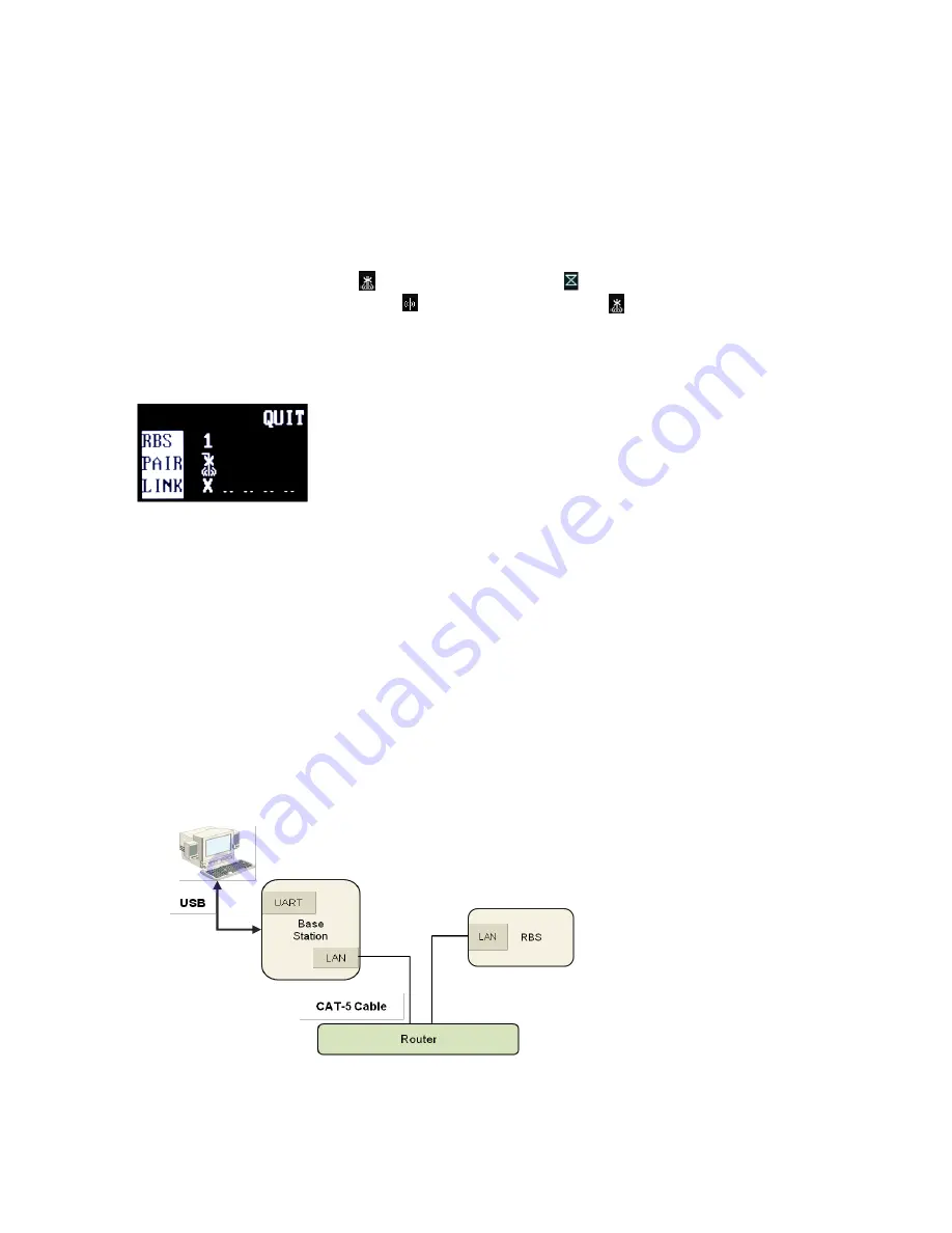
When you use the network switching device which has the POE function:
Connect CAT-5 cable to LAN
Connector (#7) of Remote Base Station and connect the other side to network switching
device which has the POE function.
Upon the power supply, the green light should go on. In case of using battery, when the battery level is low, red light will
go on.
3) IMPLEMENT THE PARING UP PROCESSING
On the MAIN
menu of the Base Station, move to and select “RBS”. The RBS menu appears as shown in Figure 3-26.
Using LEFT or RIGHT button, m
ove to the number, „1‟ next to „RBS‟ on the RBS menu for paring up and press SET on it
then, the corresponding pairing icon, ( ) in the next row is changed to ( ), indicating the paring is being processed. If
paring processing is completed successfully, ( ) icon is displayed and if failed, ( ) is displayed in the RBS menu.
When the paring processing is completed between Base Station and Remote Base Station, the RBS LINK light on the
front panel of the Base Station will go on and the RBS Active light will be blinking when there are data transmissions.
Once paring up process is completed, reboot both the Base Station and Remote Base Stations.
NOTE 1
The RBS LINK light on the Base Station will go on if there is a Remote Base Station linked in.
NOTE 2
The link status of the Remote Base Stations can be confirmed in the RBS menu as shown in the Figure 3-26. When the
Remote Base Station is linked in,
“O” is displayed and is not linked, “X” is displayed.
NOTE 3
During the pairing process, all the connections for communications are off.
Step 3
: Wire the Base Station with the Remote Base Station for actual operation as shown from the Figure 3-27.
Figure 3-27. Connections example
Figure 3-26. RBS menu
34


