LPMVC-CL025M Manual
More than Imaging – Laon People
27
2016-03-04
4.7.
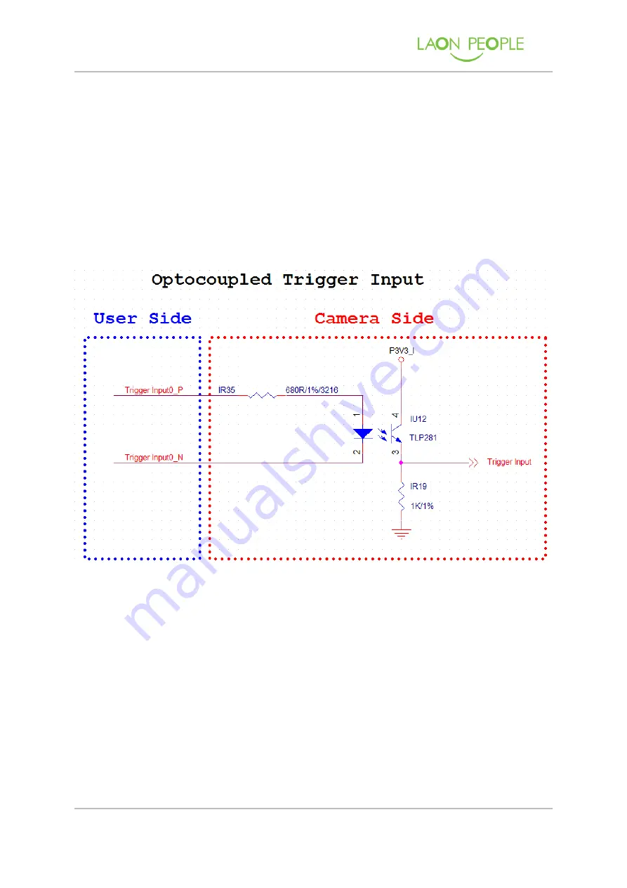
Trigger Input Circuit
Figure 12 represents the trigger input circuit. Input trigger signal is passed to the
internal circuit through the photo coupler.
1
㎲
is the minimum width of the trigger signal which the camera can recognize. If the
width of the trigger signal is shorter than 1
㎲
, camera ignores this signal. The Trigger
Input Voltage supports up to +24V (Industrial standard level), but it is recommended to
use +5V (TTL signal level).
Figure 13. LPMVC-CL025M Trigger Input circuit


