background image

9: Services

Spider™ and SpiderDuo® KVM-over-IP Device User Guide

91

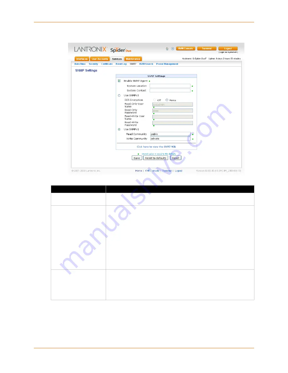
Figure 9-6  SNMP Settings Page

2. Modify the following fields.

3. Do one of the following:

a. Click 

Save

 to save settings. 

b. Click 

Reset to Defaults

 to restore system defaults. 

c. Click 

Reset

 to restore original settings.

Field

 Description

Enable SNMP Agent

Click the checkbox to enable the Spider device SNMP agent, and enter the 
system location and the contact name for the system.

Use SNMPv3

Select to use SNMPv3 (rather than SNMPv1)and enter the following:

DES Encryption:  

Select whether to turn off or enable encryption with 

Data Encryption Standard (DES),

Read Username: 

 User ID for a user with read-only authority to use to 

access SNMP v3.

Read Password

:  Password for a user with read-only authority to use to 

access SNMP v3. Up to 32 characters.

Write Username

: Enter a user ID for users with read-write authority. Up to 

32 characters. 

Write Password

: Enter a password for the user with read-write authority 

to use to access SNMP v3. Up to 20 characters.

Use SNMPv1

Select to use SNMPv1 (rather than SNMPv3) and enter the following:

Read Community:

 Enter the SNMP read community name. The default is 

public

.

Write Community:

 Enter the SNMP write community name. The default 

is 

private

.

Summary of Contents for Spider

Page 1: ...Part Number 900 495 Revision G November 2013 Spider and SpiderDuo KVM over IP Devices User Guide ...

Page 2: ...GPL as published by the Free Software Foundation and may be redistributed and modified under the terms of the GNU GPL A machine readable copy of the corresponding portions of GPL licensed source code is available at the cost of distribution Such source code is distributed WITHOUT ANY WARRANTY INCLUDING ANY IMPLIED WARRANTY OF MERCHANTABILITY OR FITNESS FOR A PARTICULAR PURPOSE See the GNU General ...

Page 3: ...anufacturer could void the user s authority to operate this equipment Changes or modifications to this device not explicitly approved by Lantronix will voids the user s authority to operate the device Documentation Changes The information in this guide may change without notice The manufacturer assumes no responsibility for any errors that may appear in this guide For the latest revision of produc...

Page 4: ..._________________16 Functionality __________________________________________________________17 System Configuration and Cables _________________________________________17 Technical Specifications _________________________________________________19 SpiderDuo Overview _______________________________________________________20 Features _____________________________________________________________20 Fu...

Page 5: ..._________45 6 Remote System Control 46 Overview ________________________________________________________________46 Remote Console Window ___________________________________________________46 Main Viewport and Scroll Bars ___________________________________________47 Button Keys __________________________________________________________47 Toolbar ____________________________________________________...

Page 6: ...______________________58 IPv6 Settings Firmware v3 0 or higher _____________________________________58 Miscellaneous Network Settings ___________________________________________58 Serial Port Settings ________________________________________________________60 KVM Console Settings _____________________________________________________61 KVM Console Settings __________________________________________...

Page 7: ...____________82 9 Services 83 Date Time _______________________________________________________________83 Security _________________________________________________________________84 HTTP Encryption ______________________________________________________85 Login Limitations _______________________________________________________85 KVM Encryption ______________________________________________________...

Page 8: ...up Commands ___________________________________________________112 OEM Customization Commands _____________________________________________115 Power Commands ________________________________________________________115 Serial Port Commands ____________________________________________________116 WOL Wake on LAN Commands ____________________________________________116 USB Host Disk Commands _________...

Page 9: ...30 Input Supply ____________________________________________________________130 Grounding ______________________________________________________________130 Fuses _________________________________________________________________130 Appendix F Technical Support 131 Technical Support US __________________________________________________131 Technical Support Europe Middle East Africa _________________...

Page 10: ...______36 Figure 4 5 SpiderDuo Default IP Configuration Screen ___________________________________36 Figure 4 6 Lantronix Detector Window ________________________________________________38 Figure 4 7 Detector Device List Window_______________________________________________38 Figure 4 8 Network Settings Window _________________________________________________39 Figure 4 10 PCU Layout and Dimensions...

Page 11: ..._____________________________________________81 Figure 9 1 Date Time Settings Page__________________________________________________83 Figure 9 3 Security Settings Page ___________________________________________________85 Figure 9 4 Certificate Signing Request Page ___________________________________________87 Figure 9 5 Event Log Page _________________________________________________________89 F...

Page 12: ...ications _________________________________________22 Table 3 2 Spider LEDs ____________________________________________________________27 Table 4 3 SpiderDuo Indicator LEDs _________________________________________________36 Table 4 9 Extended Length Cables __________________________________________________41 Table 9 2 Date Time Settings ______________________________________________________84 Tab...

Page 13: ...e Provides technical specifications describes connection formats and power supplies Chapter 4 Installing the SpiderDuo Device Provides technical specifications describes connection formats and power supplies Chapter 5 Web Browser Access Describes method to access the Web browser Chapter 6 Remote System Control Describes the remote system control Chapter 7 Interfaces Provides instructions for confi...

Page 14: ...Compliance Provides information about the Spider and SpiderDuo device compliance with industry standards Table 1 2 Conventions Used in This Book Convention Description Bold text Default parameters Brackets Optional parameters Angle Brackets Possible values for parameters Pipe Choice of parameters Warning Warning Before you work on any equipment you must be aware of the hazards involved with electr...

Page 15: ...ww lantronix com support documentation for the latest documentation and the following additional documentation Spider View User Guide Details instructions on using the Spider View utility Spider Quick Start Guide Provides an overview of using the Spider device SpiderDuo Quick Start Guide Provides an overview of using the SpiderDuo ...

Page 16: ...terms Remote Console and KVM Console are synonymous and used interchangeably throughout the User Guide Spider Overview The Spider device features functionality system configuration and cables and technical specifications are described in the following sections Features Functionality System Configuration and Cables Technical Specifications Features The Spider device is unique in that it is low enou...

Page 17: ...sign no external power supply required Lantronix SwitchPort technology allows Spider devices to be cascaded or share a host Ethernet connection Functionality The Spider device captures the video output from the attached computer compresses and sends it over the network to a Java KVM console window launched by the browser or to a command line interface on the user system which displays a replica of...

Page 18: ...2 Overview Spider and SpiderDuo KVM over IP Device User Guide 18 Figure 2 1 Spider System Configuration Figure 2 2 Spider Cable Dimensions ...

Page 19: ...he Spider device hardware is an earlier revision it will only support up to 1280 x 1024 resolution at 60 Hz The hardware revision number can be found on the Product Information Label as shown in Figure 2 8 Client System Requirements SUN Java Runtime Environment JRE 1 4 or later Optional Items Replacement mounting bracket kit see Chapter 4 Mounting Bracket Kit Optional DC power supply with internat...

Page 20: ...s lowest cost per remote user Browser based no client software or special licensing required Virtual Media support allows local drive floppy CD hard drive USB stick sharing with a remote server or remote installation of an OS from an ISO image Direct KVM minimizes the number of clicks to the remote server console Built in RS 232 serial port that can be configured for serial console pass through or...

Page 21: ...tion and Cables Figure 2 4 shows an SpiderDuo system configuration Figure 2 5 shows the PS 2 cable dimensions and Figure 2 6 shows the USB cable dimensions Figure 2 4 SpiderDuo System Configuration Figure 2 5 shows the PS 2 cable dimensions Figure 2 5 SpiderDuo PS 2 Cable Dimensions ...

Page 22: ...ouse and video data IP Source Address Filtering Remote Authentication LDAP RADIUS Active Directory User Group management with permissions control Configurable port numbers HTTP HTTPS Telnet SSH Selective disable of Telnet SSH Target Server Requirements Multiple Operating Systems supported Windows 98 2000 2003 XP Vista Unix Linux or MAC OSX 10 Power keyboard mouse 2 USB ports or 1 USB and 1 PS 2 ke...

Page 23: ...n part number 500 200 R Interfaces Network 10 100Base T Ethernet Port with activity indicators RJ45 Serial RS 232 up to 115 200 bps for serial device pass through unit configuration or PCU controller USB Local KVM connector Computer input connector Environmental Operating 0º to 45º C 32º to 115º F Storage 20º to 70º C 4º to 158º F Humidity 0 to 95 RH non condensing Heat Dissipation 4 Watts 14 BTU ...

Page 24: ...2 Overview Spider and SpiderDuo KVM over IP Device User Guide 24 Figure 2 8 Spider Family Product Information Label ...

Page 25: ... of the Spider device USB Keyboard and Mouse Interfaces Provides better remote cursor tracking Some older systems may not support USB devices or there may not be two USB ports available In these cases the PS 2 interface model may be required You configure either interface by using the software Serial Ports Performs the initial configuration to setup parameters and connects to a target COM port It ...

Page 26: ...n a single LAN cable can provide connectivity to the Spider device and server conserving a switch or router port Aggregate any other Ethernet connection as a general purpose switch port Batch vs Individual Setup Deploying a batch of Spider devices at once should be performed as a stage before attaching to the computers The staging can be performed on a bench prior to configuration Consider the fol...

Page 27: ... 8 Follow the prompts to enter the IP address subnet mask default gateway and LAN interface information as shown in Figure 3 4 Figure 3 4 Spider Prompts 9 Type Y and press Enter to accept the changes The system takes several seconds to update the internal protocol stack and display the updated information See Detector Installation and IP Address Reset on page 28 for more information about using De...

Page 28: ...ou need to change your security settings using the NET Framework Configuration or caspol tool Perform the following steps to install Detector 1 Double click detector2 exe on its CD If you see this error message The application failed to initialize properly 0xc0000135 click OK to terminate the application and install NET Framework Go to Step 2 2 Copy the NET Framework application from Lantronix at ...

Page 29: ...imeout drop down menu The default is 3000 6 Click the Search icon A list of Lantronix Ethernet devices on the network displays as shown in Figure 3 7 Figure 3 7 Detector Device List Window 7 Click to highlight the device that you want and click the Network Settings icon to change the IP address The Enter Network Settings window displays the Device Type and MAC Address Ethernet address that identif...

Page 30: ...nd the device in this list and verify the IP address You can access the device by using its new IP address Note On the Interfaces Network page of the web interface make sure Disable Setup Protocol is not selected in the Network Miscellaneous Settings section Target Computer Setup Setting up the target computer involves ensuring that the video resolution and refresh rates are correct for the target...

Page 31: ... appearances do not have any particular limitations Microsoft Active Desktop and Linux virtual desktop are not supported If bandwidth is a concern plain backgrounds are preferred If you are using a special video card or OS consult the documentation Mouse to Cursor Synchronization Mouse to cursor synchronization can be an issue with digital KVM interfaces because PS 2 mice transmit incremental info...

Page 32: ...g the Spider serial port plug the cable into the COM port on the server The second Cascade Ethernet port can connect to the Spider device to the target computer management LAN port or to a main LAN port or to a Spider device chain When connecting the Ethernet ports straight through or crossover cables can be used because the Spider device has auto polarity and auto crossover correction Although th...

Page 33: ...un the Remote Console window and manage the target server a Java plug in SUN JRE 1 4 or later is required Network Environment The connection between the client and Spider device must be open to IP traffic and use TCP ports 80 HTTP and 443 HTTPS Firewalls and NAT devices should be configured to support this configuration The TCP ports can be changed by accessing Interfaces Network When idle minimal...

Page 34: ... AC Power Cables 1830 30 mm 72 1 2 in Local KVM cable Computer Input cable Mounting kit See Appendix D Mounting Bracket Kit Quick Start Guide CD ROM containing documentation and utilities External AC DC Power Supply Optional power control unit PCU100 01 Warning The connectors on the SpiderDuo device are not regular video connectors To avoid damage to the SpiderDuo device do not connect cables of a...

Page 35: ...s one port only that connects to the LAN Local KVM Port Connects keyboard video and mouse to the local client Perform the following steps to install the SpiderDuo device and configure the initial network settings 1 Plug the RJ45 cable into the SpiderDuo serial port 2 Plug the DB9F end of the RJ45 cable into the COM port of a PC laptop running a terminal emulator for example HyperTerminal The defau...

Page 36: ... 7 Follow the prompts to enter the IP address subnet mask default gateway and LAN interface information 8 Type Enter to accept the changes The system takes about 20 seconds to complete Type Enter once again at the prompt to display the updated IP address 9 Plug an Ethernet cable connected to your network into the Ethernet port The Link LED illuminates Pinouts 1 RTS out 2 PCU 5V out 3 TX out 4 PCu ...

Page 37: ...ort downloads html Note Lantronix recommends that you run Detector downloaded from Lantronix at http www lantronix com support downloads html and run it from there rather than from a shared network drive Otherwise you may get a security exception If you must run the program from a shared network drive you need to change your security settings using the NET Framework Configuration or caspol tool Pe...

Page 38: ... the number in the Timeout drop down menu The default is 3000 6 Click the Search icon A list of Lantronix Ethernet devices on the network displays as shown in Figure 4 7 Figure 4 7 Detector Device List Window 7 Click to highlight the device that you want and click the Network Settings icon to change the IP address The Enter Network Settings window displays the Device Type and MAC Address Ethernet ...

Page 39: ...device in this list and verify the IP address You can access the device by using its new IP address Note On the Interfaces Network page of the web interface make sure Disable Setup Protocol is not selected in the Network Miscellaneous Settings section Target Computer Setup Setting up the target computer involves ensuring that the video resolution and refresh rates are correct for the taget compute...

Page 40: ...p are not supported If bandwidth is a concern plain backgrounds are preferred Mouse to Cursor Synchronization Mouse to cursor synchronization can be an issue with digital KVM interfaces because PS 2 mice transmit incremental information about movement over a period of time rather than an absolute measurement The OS driver translates acceleration to distance based on the local screen resolution and...

Page 41: ...t on the server Available extended length cables are shown in Table 4 9 Power Sequencing To ensure that the system PC local keyboard and mouse and SpiderDuo device function properly at power up it is recommended that the following procedure be performed 1 Ensure that the PC and SpiderDuo are powered off 2 Make connections for all devices 3 Turn on the SpiderDuo first and wait for the SpiderDuo to ...

Page 42: ...n SUN JRE 1 4 or later is required Network Environment The connection between the client and SpiderDuo device must be open to IP traffic and use TCP ports 80 HTTP and 443 HTTPS Firewalls and NAT devices should be configured to support this configuration The TCP ports can be changed by accessing Interfaces Network When idle minimal network traffic gets generated Traffic bursts exceeding 10 Mpbs can...

Page 43: ...d other equipment In addition the user can restart or power cycle the PC and other equipment shows the layout and dimensions of the PCU Figure 4 10 PCU Layout and Dimensions Complete the following tasks to connect the PCU 1 Connect the power output plug to a target PC or other equipment 2 Connect the RJ45 cable from the PCU to the SpiderDuo serial port 3 Connect the power input plug to AC power Gr...

Page 44: ... and SpiderDuo KVM over IP Device User Guide 44 Warning AC power passes through by default if the RJ45 cable is disconnected from the PCU The SpiderDuo device gets its power from an external DC supply Replacement power supplies are available ...

Page 45: ...ord default is PASS at the prompt The home page displays From the home page the Remote Console or Telnet Console can be launched as shown in Figure 5 1 Figure 5 1 Spider device Home Page The home page contains the following items Snapshot of the target system video in the KVM Console Preview window in the center Session and host name information Tabs called Interfaces User Accounts Services and Ma...

Page 46: ...computer window displays in the Remote Console window mouse movements and keystrokes are transmitted to a remote computer The title bar of the window shows the IP address of the Spider device or SpiderDuo useful when multiple windows are open on the client system The Remote Console window can be minimized maximized or scaled in either direction There are Main viewport and scroll bars button keys a...

Page 47: ...w Button Keys Along the top there are Button Keys that have been defined to send special key codes directly to the target computer Toolbar The top toolbar has a number of buttons for one click access to functions and a drop down menu where other options may be reached The icons vary depending on which keyboard interface is active Access Virtual Media The left most diskette icon is used to activate...

Page 48: ...sed of keystrokes and mouse movements When the target screen is not changing In should be low or zero If not click the auto adjust button The amount of network traffic is a function of the detail in the captured screen the rate at which the screen is changing and the video encoding settings Concurrent Access State One user is connected to the Remote Console Multiple users are connected to the Remo...

Page 49: ... but outside the viewport interaction is with the Remote Console control functions such as the toolbar or scroll bars Figure 6 2 Remote Console Window Within the Remote Console viewport interaction with the remote computer is generally the same as if there were a direct connection with a minor lag due to network latency Windows may be opened applications run settings changed maintenance functions ...

Page 50: ...t be feasible The Spider device provides a mode where only one cursor is visible when operating in the active Remote Console viewport Click the Single Double button on the toolbar to activate Single Mouse Mode This is indicated by a single arrow in the Single Double button When in this mode the Java KVM console grabs the local cursor after clicking within the viewport and will not release it until...

Page 51: ...ess and contrast of the Remote Client window as presented by the Auto Adjustment This is a hardware parameter and applies to all Spider users Overall brightness and the contrast levels of each of the red green and blue primaries may be modified up or down The Remote Console window immediately reflects the change Once there is a satisfactory color mapping click Save Changes to retain those colors p...

Page 52: ...e local keyboard without worrying about OS and application character set mappings Select Options Soft Keyboard Mapping to get a submenu listing the languages supported Make the desired selection and then verify it with Show soft keyboard Select Options Soft Keyboard Show This provides an image of the currently selected Soft Keyboard The Soft Keyboard sends single keystrokes as well as combinations...

Page 53: ...plications Refresh Video The entire Remote Console viewport area is redrawn when the Remote Console window is first opened and when the Auto Adjust Video button is clicked As the encoding settings and noise filter may sometimes result in visible compression artifacts selecting Options Refresh Video can be used to redraw the entire viewport area Telnet SSH In addition to interacting with the target...

Page 54: ...list of commands Version Displays the current Spider firmware version number Connect Serial Enter passthrough to serial port mode Logout Terminates the Telnet or SSH connection 4 Enter connect serial to open the connection to the serial port 5 You are now connected and may interact with the attached serial console Keystrokes are not locally echoed and must be echoed by the connected serial device ...

Page 55: ...6 Remote System Control Spider and SpiderDuo KVM over IP Device User Guide 55 Figure 6 4 Login Screen ...

Page 56: ... connection This occurs when you click Save Ensure that your new settings are correct when making changes from a remote site before you click Save In Network Settings there are four configuration areas Network Basic Settings Sets auto IP configuration host name IP address subnet mask gateway address and primary and secondary DNS server addresses IPv6 Settings Enables IPv6 LAN Interface Settings Se...

Page 57: ...with a short host name or a fully qualified domain name IP address If you are using a fixed IP address enter it in the usual dot notation Subnet Mask If you are using a fixed IP address enter the subnet mask of the local network Gateway IP address optional If the Spider device is to be accessible from outside the local subnet enter the IP address of the router providing access Primary DNS Server I...

Page 58: ...Pv6 is selected IPv6 address dynamic Assigned automatically by the system Link local IPv6 address Network address intended only for communications within one segment of a local network or a point to point link Assigned automatically by the system Field Description Remote Console HTTPS port Port number at which the Spider device Remote Console server and HTTPS server are listening The default is 44...

Page 59: ...ses As a security measure you may wish to disable this protocol when deploying Spider devices If the protocol is disabled Detector and the Spider device network will not find the Spider device Enable remote console proxy access Enable the Java KVM console program to use a proxy server to connect to the Spider device If you must configure your web browser to use a proxy server you will likely have ...

Page 60: ...o log into and operate the Spider device If you want to access a console port remotely through the Spider device SSH and Telnet passthrough is available To configure the serial port perform the following steps 1 Click Interfaces Serial Port The Serial Port Settings page displays Figure 7 2 SpiderDuo Serial Port Settings Page 2 Modify the following fields Field Description Configuration Login Selec...

Page 61: ...signed to the remote device Modem client IP address IP address assigned to the Spider device Passthrough Access to serial port 1 via Telnet SSH The serial port may be used to connect to the target server s COM port for integrated access to command line functions or used to control a serial interfaced peripheral Telnet and SSH are network protocols that enable a tunnel from the client system over t...

Page 62: ...ions these parameters are applied on a user by user basis The default is set for maximum image quality and speed of updates which results in high data rate and hence is suitable for LANs where bursts of up to 2 Mbytes second are acceptable To modify the user console perform the following steps 1 Click Interfaces KVM Console The Remote Console Settings for User page displays Figure 7 3 User Remote ...

Page 63: ...pth will be configured accordingly Manual Allows the direct control of the compression factor and color depth The simplest way to reduce bandwidth is to cut the color depth down to 8 bits subtle color shades will be gone but the overall image is very usable Dialing up the compression level also makes available even further reductions in color depth all the way down to black and white 1 bit As comp...

Page 64: ...me aspect ratio Press Ctrl F10 again to return to regular screen mode The default is Ctrl F10 Change the key code if necessary Field Description Key Definition Help Button keys allow simulating keystrokes at the remote system that cannot be generated from the client keyboard A flexible syntax allows for combinations of keys being clicked in combination or in sequence with optional pauses and an op...

Page 65: ... Device User Guide 65 Keyboard Mouse To modify the keyboard and mouse settings perform the following steps 1 Click Interfaces Keyboard Mouse The Keyboard Mouse Settings page displays Figure 7 4 Keyboard Mouse Settings 2 Modify the following fields ...

Page 66: ...SB Full Speed Mode Some older systems do not support USB high speed mode and may not recognize the keyboard mouse Enable this option for Spider device to negotiate in USB full speed mode Field Description PS 2 keyboard model drop down menu When operating in PS 2 interface mode key codes from several layouts may be emulated Generic 104 key PC for the traditional layout Generic 109 key PC for keyboa...

Page 67: ...ick enabled and use the Country drop down list to select your language choice Note Sun Solaris settings are for the Spider device only 4 Click Save Field Description USB mouse type drop down menu Different operating systems running on the target system require different mouse emulation protocols One selection is available for newer versions of Windows and Mac OS X and another for Other Operating S...

Page 68: ... an update to the client system This can result in a constant stream of data even when the image on the target computer s screen is not moving In order to avoid this at Interface Video Miscellaneous Video Settings the Spider device has a selection for noise filter The larger filter openings will filter out more of the noise at the cost of potentially missing small incremental changes and seeing so...

Page 69: ...network connection With Floppy Disk Image the user can upload an image to the Spider device s memory which then emulates a locally attached floppy drive With CD ROM Image a Windows or other SAMBA share can emulate a locally attached CD ROM for instance to update software Drive Redirection allows you to share redirect your local drive floppy drives hard disks CD ROMs and other removable devices lik...

Page 70: ...ge information about the currently assigned active image displays Field Description Disable Drive Redirection Drive Redirection is enabled by default Select this checkbox to disable the ability to share the local drive with the remote system Force read only connections Select to prevent the remote drive from writing to your local drive Selected by default Warning Clearing the Force read only conne...

Page 71: ...mounted until the current user logs out or the Spider device is rebooted Other client systems logging into the Spider device will see the active image in all Virtual Media pages To share a CD ROM image perform the following steps 1 Enter the following fields 2 Do one of the following a To discard your changes click Reset Field Description Disable USB Mass Storage Select the checkbox to disable USB...

Page 72: ...e Spider device which then appears to the attached computer as a physical floppy drive The desired floppy image file will be uploaded from the client system or from a network drive accessible to the client system The file must be structured as a floppy image To make a floppy image search for and use a utility such as dd or rawwrite The maximum image size is 1 44 MB For larger images use the CD ROM...

Page 73: ...ognize the image b Click Download to save the image file c Click Discard to remove the current image file Connecting to a Redirected Drive If Drive Redirection is enabled you can connect to the drive Depending on the combination of the type of drive and the Force read only connections setting different warnings display To connect to a redirected drive perform the following steps 1 Click the KVM Co...

Page 74: ...redirect Note To refresh the list after adding or removing a drive click the Refresh List button 5 If desired select the Enable Write support check box 6 Click OK Depending on your selections the following events or warnings display 7 If you select Enable Write support the following warning displays Figure 7 13 Enable Write Support Window Because of the danger of destroying all data on the drive c...

Page 75: ...ss Open Figure 7 15 Drive Redirection Established Window 9 ISO Drive Redirection established displays at top of screen User Interface Settings The color of page tabs on the Spider device can be changed On the Interfaces page click UI Select a style sheet from the drop down list on the User Interface Settings page Click Save Figure 7 16 User Interface Settings Page ...

Page 76: ...vice a user must be authenticated by means of a password This authentication may take place locally where the user name and associated password are stored in the Spider device s memory The Spider device may query a centralized database using RADIUS or LDAP to determine if a given user may log in In both of these cases the user name must be defined on the Spider device where it has its permissions ...

Page 77: ...click Reset to restore original settings User and Group Management You must be logged in under a user name that has permissions for User Group Management to access this page The Spider device supports a maximum of 50 configured users When defining a user make sure the group to which the user will belong has already been created To configure users and groups perform the following steps 1 Click User...

Page 78: ...iption Existing users To modify or copy an existing user select that user from the drop down menu and click Lookup New user name Enter the new user s name Minimum 1 character Full user name Enter the full name of the configured user Minimum 1 character Password Enter the password for the user Minimum 4 characters Confirm Password Re enter the password for the user Email address Optional Enter the ...

Page 79: ... to delete an existing group e Click Reset to restore original settings User Permissions To modify user permissions perform the following steps 1 Click User Accounts Permissions The User Group Permissions page displays Figure 8 3 User Permissions Page 2 From the drop down menu select Group to configure 3 If you created a user belonging to a group and you want to change permissions for the group se...

Page 80: ...step 4 6 Modify the displayed permissions as necessary for the selection 7 Do one of the following a Click Save to save settings b Click Reset to Defaults to restore system defaults c Click Reset to restore original settings Remote Authentication If the authentication settings have been set to Local Authentication the default the Spider device uses its own database to perform authentication If one...

Page 81: ...tion is selected the Spider device will authenticate against its internal database of users and passwords as described in Local User Management Field Description LDAP Server IP Enter the name or IP address of the LDAP server reachable over the network by the Spider device containing the user database Be sure to configure a DNS server if a name rather than address is used LDAP Server Base DN Specif...

Page 82: ...achable over the network by the Spider device containing the user database Configure a DNS server if a name rather than an address is used Shared Secret A shared secret is a text string that serves as a password between the RADIUS client and RADIUS server In this case the Spider device acts as a RADIUS client A shared secret is used to verify that RADIUS messages are sent by a RADIUS enabled devic...

Page 83: ...clock that maintains a basic date and time after being set The clock however will reset if the unit loses power If an accurate date and time are critical the Spider device supports synchronization with Network Time Protocol servers Internally the date and time are only used to timestamp events in the log and for the inactivity timeout To configure the date and time settings perform the following s...

Page 84: ...ings perform the following steps 1 Click Services Security The Security page displays Table 9 2 Date Time Settings Field Description UTC Offset Time servers deliver time as Coordinated Universal Time UTC or Greenwich Mean Time Select the appropriate offset in hours from the drop down menu User Specified Time Manually input the current date and time The Spider device keeps time as long as power is ...

Page 85: ...ion on how the Spider device identifies itself using a cryptographic certificate Field Description Enable Single Login Limitation If this box is checked each username may only have one logged in connection at a time If unchecked multiple instances of username logins are allowed Field Description KVM Encryption In addition to the SSL encryption of the Spider device s web pages the keyboard mouse an...

Page 86: ...oups are defined in User Management Users Group Management they will appear in the drop down A rule can apply to only one group at a time Action Chooses whether this is to be a Drop or Accept rule After a rule has been defined it needs to go in the correct place in the list Append Puts the rule at the end of the list The rule number changes to reflect the last position on the list Insert Puts the ...

Page 87: ...der device The Spider device is able to generate a new cryptographic key and the associated Certificate Signing Request CSR that needs to be certified by a certification authority CA To create and install an SSL certificate perform the following steps 1 Click Services Certificate The Certificate Signing Request page displays Figure 9 4 Certificate Signing Request Page 2 Modify the following fields...

Page 88: ...tself to its clients State Province The state or province where the organization is located Country ISO code The country where the organization is located This is the two letter ISO code e g US for the United States Email The email address of a contact person responsible for the Spider device and its security Challenge password Confirm Challenge password Certain certification authorities require a...

Page 89: ...odify the following fields Event Log Targets Field Description List Logging Enabled Check this box to use the internal log list of the Spider device The maximum number of entries is 1 000 Every entry that exceeds this limit overrides the oldest one The number of log entries shown on each page may be changed in the text box The internal log list is cleared when power is removed from the Spider devi...

Page 90: ...ettings page displays SMTP Logging enabled With this option the Spider device is able to send emails to an address given by the email address These emails contain the same description strings as the internal log file and the mail subject contains the event class To use this log destination specify an SMTP Server the Receiver Email Address and Sender Email Address Enter the mail server and SMTP por...

Page 91: ...ng DES Encryption Select whether to turn off or enable encryption with Data Encryption Standard DES Read Username User ID for a user with read only authority to use to access SNMP v3 Read Password Password for a user with read only authority to use to access SNMP v3 Up to 32 characters Write Username Enter a user ID for users with read write authority Up to 32 characters Write Password Enter a pas...

Page 92: ... the network The following items display IP address Hostname Direct KVM Preview Terminal SSH Telnet MAC Address Model Version Description Note The information shown on the web interface represents a snapshot in time To see the most recent data click Refresh To view a KVM search perform the following steps 1 Click Services KVM Search The search results display ...

Page 93: ...ou to manage the properties of the power system It enables the monitoring of the Power Control Unit PCU that only applies to the SpiderDuo and the sending of Wake On LAN WOL messages to a computer that has WOL enabled To view the Power Management page perform the following steps 1 Click Services Power Management The Power Management page displays ...

Page 94: ...reboot To enable the PCU perform the following steps 1 Click Enable A warning displays requesting that you confirm 2 Click Confirm Enable The message that the enable was successful 3 Reboot for the change to take effect Wake On LAN Wake On LAN WOL sometimes WoL is an Ethernet computer networking standard that allows a computer to be turned on or woken up remotely by a network message sent usually ...

Page 95: ...system can sometimes control the WOL behavior Refer to your motherboard and operating system user guide for configuration information Enable WOL To enable WOL perform the following steps 1 Enter the MAC address and password in the Send to the MAC address below field 1 Click Wake Up Or 2 Enter the device name IP address MAC address and password in the Send to the following devices field 3 Click Add...

Page 96: ...tting the unit It contains the following sections Device Status Configuration Update Firmware View Event Log Unit Reset iGoogle Gadgets Device Status The Device Status page contains a table with information about the Spider device s hardware and firmware This information is useful if technical support is required To view device information perform the following steps 1 Click Maintenance Device Sta...

Page 97: ...lays Table 10 2 Device Status Settings Field Description Device Information Displays the product name serial number board ID device IP address device MAC address firmware version firmware build number firmware description hardware and Kira chip revision Connected Users Displays the user name and IP address of the active connection It also displays whether the user is connected to the Remote Consol...

Page 98: ...re from config file saved on your computer radio button You can then browse to and select the saved configuration file In the Preserve Following Settings field click Network Basic Click the Network Basic checkbox to preserve the current network basic settings on the Network Settings page and import only the remaining settings from the configuration file Click the Upload button If you select this o...

Page 99: ...Download the firmware file to the client system local drive or an accessible network drive 2 Click Maintenance Update Firmware The Firmware Update page displays Figure 10 4 Update Firmware Page 3 Click Browse In the pop up window navigate and locate the firmware file 4 Click Upload to copy the file into the Spider device s local memory When uploaded correctly the Firmware Upload window displays th...

Page 100: ...et In general the Spider device requires a reset when implementing a firmware update In the event of an abnormal operation a number of subsystems may be reset without resetting the entire Spider device To reset the Spider device perform the following steps 1 Log into the Spider device as sysadmin 2 Click Maintenance Unit Reset The following page displays ...

Page 101: ...in to the Spider device Technically the number of Spider devices that can be viewed and accessed on one web page is unlimited It is important to note that the more Spider devices that are added the slower the response time will be Anyone with a Google email account gmail com can create an iGoogle gadget for viewing web pages There are two types of iGoogle gadgets public gadgets and private gadgets...

Page 102: ...device IP address screenshot jpg border 0 width 320 height 240 onclick window open https your Spider device IP address div script var c 0 var t function updateSpiderSnapshot document getElementById sp_img src http your Spider device IP address screenshot jpg rnum c c c 1 t setTimeout updateSpiderSnapshot 60000 60 sec updateSpiderSnapshot script Content Module 4 Upload the edited xml file spider1 x...

Page 103: ...10 Maintenance Spider and SpiderDuo KVM over IP Device User Guide 103 Figure 10 7 iGoogle Gadget Page ...

Page 104: ... parameter s is one or more name value pairs in one of the following formats parameter name aa bb Specify one of the values aa or bb separated by a vertical line The values are all lowercase and must be entered exactly as shown Bold indicates a default value parameter name Value Specify an appropriate value for example a device group name This User Guide shows parameter values in mixed case to ind...

Page 105: ...ce by pressing the Backspace key or the Delete key depending on how you accessed the interface Both keys work if you use VT100 emulation in your terminal access program when connecting to the console port Use the left and right arrow keys to move within a command Use the up and down arrows to scroll through previously entered commands If desired select one and edit it You can scroll through up to ...

Page 106: ...ults Note The unit reboots after this command All current settings are lost admin config show Syntax admin config show Parameters None Description Shows the current configuration admin config save Syntax admin config save Parameters None Description Saves the current configuration Note Each time you use the admin config save command the existing config_save file is overwritten admin config restore...

Page 107: ...hkey delete keyuser SSH Key User keyhost SSH Key Host Description Deletes an imported SSH key Examples To delete an imported SSH public key on host pipe for the sysadmin user enter the following CLI set sshkey delete keyuser sysadmin keyhost pipe set sshkey import Syntax set sshkey import copypaste format openssl keyuser SSH Key User keyhost SSH Key Host Description Imports public SSH key OpenSSH ...

Page 108: ...the following CLI show sshkey viewkey enable To displays an imported SSH public key on host pipe for the sysadmin user enter the following CLI show sshkey keyuser sysadmin keyhost pipe History Commands set history clear Syntax set history clear Description Clears the CLI command history show history Syntax show history Description Displays the 100 most recent CLI commands Network Commands set netw...

Page 109: ...isc Syntax set network misc parameters Parameters bwlimit 8 10000 kbit s httpsports TCP Port httpport TCP Port proxy enable disable proxyhost IP Address proxyport TCP Port telnet enable disable telnetport TCP Port setupprotocol enable disable ssh enable disable sshport TCP Port Description Sets miscellaneous network parameters set network interface set network interface parameters Parameters mode ...

Page 110: ...rk misc Description Displays network miscellaneous parameters show network interface Syntax show network interface Description Displays network interfaces show network all Syntax show network all Description Displays all network settings Version Command admin version Syntax admin version Description Displays firmware version information Date Time Command set datetime Syntax set datetime one parame...

Page 111: ...Sets the date and time or UTC offset show datetime Syntax show datetime Description Shows the date time and UTC offset User Commands set user Syntax set user add edit User Login parameters Parameters email Email Address fullname Full Name group Group Name default Admin None mobile Phone Number Note The group default Unknown and Admin and are built in groups The group None indicates that user is cr...

Page 112: ...yntax set user password User Login Description Sets user password show user name Syntax show user name user User Login Description Displays user names show user Syntax show user index Index Number Description Displays index numbers User Group Commands set group Syntax set group add edit Group Name parameters Parameters permissions Permission List Description Configures user groups See Group Permis...

Page 113: ...up indexes Note Group of None username indicates that user was created without defining a group and permissions will be assigned specifically to the user In order to specify a group of this type None use username as the name parameter Security Commands set security Syntax set security one or more parameters Parameters forcehttps enable disable singlelogin enable disable kvmencryption off try force...

Page 114: ...y settings user group information and basic system settings device Device Commands set device Syntax set device add edit Device Name macaddress MAC Address parameters Parameters ipaddress IP Address password Password Note MAC address must be in hex form XX XX XX XX XX XX Description Configures devices set device delete Syntax set device delete Device Name Description Deletes a device show device S...

Page 115: ...re parameters Parameters product Product Name company Company Name copyright Copyright url URL title Title Examples To set the product name as MyKVM and the company name as MyCompany enter the following CLI set oem product MyKVM company MyCompany Description Sets product company specific information on the web interface show oem Syntax show oem Description Displays OEM settings Power Commands set ...

Page 116: ...l Port Commands set serial mode Syntax set serial mode passthrough config parameters Parameters baud 300 115200 databits 7 8 stopbits 1 2 parity none odd even flowcontrol none xon xoff rts cts Description Set serial port parameters for each mode show serial Syntax show serial Description Displays serial port settings WOL Wake on LAN Commands connect wakeonlan device Syntax connect wakeonlan device...

Page 117: ...lowing USB Host Disk commands are available for the SpiderDuo device only usbhost disk mount drive Syntax usbhost disk mount drive Description Mounts a USB thumb drive to use as a storage device The USB thumb drive must be formatted with an fat filesystem and drive must support USB high speed mode usbhost disk unmount drive Syntax usbhost disk unmount drive Description Unmounts the USB thumb drive...

Page 118: ... permissions each user is a member of a group and has a set of permissions associated with the group The group permissions are defined by permissions parameters A Permission List is a comma separated list of user rights to be added to or removed from the group current permissions Precede the two letter acronym with a to remove a user right For example nt dt ka adds Networking and Date Time rights ...

Page 119: ...rd Mouse Settings ld LDAP Settings ns Network Settings pc Change Password po Power Control sn SNMP Settings sa SSH Telnet Access sm SSL Certificate Management sl Security Log Authentication ss Serial Settings us USB Settings um User Group Management vs Video Settings va Video Settings Advanced vu Virtual Media UpLoad ...

Page 120: ...not be able to transfer the video data using RFB Check the settings of the Spider device and choose a different server port used for RFB transfer A Java Runtime Environment may not be installed or may be disabled The video quality is bad or the picture is grainy Enter the Remote Console and click the Auto Adjust button to adjust the Spider device s video input parameters to the correct values Spec...

Page 121: ...ile to txt or adds a file helper using the Internet Explorer preferences for this type of file Make sure that the encoding is set to plain text and the checkbox use for outgoing is set As an alternative you may also use a Mozilla based browser Mozilla FireFox If you cannot get into the BIOS of your system or you cannot boot your system using Virtual Media try some of the following If you have a PS...

Page 122: ...vices on the network Figure B 1 Virtual Media In this example PC 2 cannot boot from its hard disk so the user wants to use the rescue CD to boot the PC We assume PC 2 can boot from external USB device Step 1 Prepare the VM Server 1 Use any CD copy application to create an ISO image of the rescue CD and call this ISO image file boot iso 2 On PC 3 Windows XP in this example put the ISO file in a Win...

Page 123: ...Firewall Properties Window Now the file boot iso can be used from a Spider device The file can be left there permanently and when a PC server crashes and cannot boot the combination of this file and the Spider device will be used to boot the PC server Step 2 Enable Virtual Media In this example PC 2 does not respond and rebooting does not cure the problem PC 2 has Spider device 2 attached 1 On any...

Page 124: ...de 124 2 Go to the Virtual Media page and complete the fields in the Image on Windows Share section of the page as shown in the diagram below Figure B 4 Virtual Media Page 3 Click Set and see that the Virtual Media Active Image section now contains data as shown in the diagram below ...

Page 125: ... 3 Use the Virtual Media 1 PC 2 shown in the diagram below is a Linux PC Figure B 6 Linux PC Window 2 Once Step 1 is done PC 2 will detect a new USB CD drive connected to its USB as shown in the diagram below The CD is shown below as Fedora Core because that is the volume name of the rescue CD boot iso is the ISO image of this CD ...

Page 126: ...rDuo KVM over IP Device User Guide 126 Figure B 7 Linux PC Window and USB CD 3 You should be able to boot from the external USB device boot iso on PC 2 Make sure that you set BIOS to boot from the USB device Note Some systems may not support USB boot ...

Page 127: ...72 75 85 832x624 75 1024x768 60 70 72 75 85 1152x864 75 1152x870 75 1152x900 66 76 1280x960 60 1280x1024 60 1600x1200 60 Note The 1600 x 1200 resolution and 60 Hz refresh rate is supported by the SpiderDuo device without conditions If a Spider device hardware is revision G22 G23 E21 or higher it will also support up to 1600 x 1200 at 60 Hz If the Spider device hardware is an earlier revision it wi...

Page 128: ...Screws The kit includes One 1 4 0 x 1 3 4 x 1 4 bracket Two 2 1 2 long 10 32 stainless steel Phillips head screws Once the mounting bracket is installed in the rack the Spider or SpiderDuo device can be easily and securely attached to the elevated mounting posts and easily removed if necessary To install the mounting bracket and Spider device into a server rack perform the following steps 1 Mount ...

Page 129: ...Table D 5 Lantronix Part Number The bracket kit is included in the box with the Spider or SpiderDuo device that ship with v2 0 firmware and later For earlier shipments the mounting kit is sold separately For additional information contact Lantronix Sales at 800 422 7055 or for technical questions contact Lantronix Technical Support at http www lantronix com support Lantronix Part Number Descriptio...

Page 130: ...stall the unit near an AC outlet that is easily accessible Always connect any equipment used with the product to properly wired and grounded power sources To help protect the product from sudden transient increases and decreases in electrical power use a surge suppressor line conditioner or uninterruptible power supply UPS connected between the AC power source and PCU Do not connect or disconnect ...

Page 131: ...e 33 1 39 30 41 72 Email mailto eu_techsupp lantronix com or mailto eu_support lantronix com Firmware downloads FAQs and the most up to date documentation are available at http www lantronix com support When you report a problem please provide the following information Your name and your company name address and phone number Lantronix model number Lantronix serial number Firmware version Descripti...

Page 132: ...the following standards or other normative documents UL CUL CSA 22 2 No 60950 1 03 UL 60950 1 CE IEC 60950 1 C Tick FCC Part 15 Equipment Class A VCCI V 3 2006 04 Class A AS NZS CISPR 22 2006 Class A EN55022 1998 A1 2000 A2 2003 Class A EN61000 3 2 2000 A2 2005 Class A EN61000 3 3 1995 A1 2001 EN55024 1998 A1 2001 A2 2003 Pb free components Warning This is a class A product In a domestic environme...

Page 133: ...imit requirement in SJ T11363 2006 Lead Pb Mercury Hg Polybrominated biphenyls PBB Cadmium Cd Hexavalent Chromium Cr VI Polybrominated diphenyl ethers PBDE Product Family Name Toxic or hazardous Substances and Elements Lead Pb Mercury Hg Cadmium Cd Hexavalent Chromium Cr VI Polybrominated biphenyls PBB Polybrominated diphenyl ethers PBDE UDS1100 and 2100 0 0 0 0 0 0 EDS 0 0 0 0 0 0 MSS100 0 0 0 0 ...

Reviews: