background image

www.lanpro.com

Wireless - Equipment - 2.4 GHz - LP-N24, 123 Manual, PTP and MTP mode Installation

3

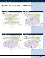
Figure 2

Figure 4

Figure 3

Figure 5

The figures 2 to 5 show examples of PTP and MTP possible connections with the LP-N24.

Summary of Contents for LP-N24

Page 1: ...Wireless Equipment www lanpro com LP N24 123 Manual PTP and MTP mode Installation LPN24_M123_ENC01W LP N24 123 Manual PTP and MTP mode Installation...

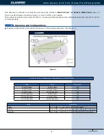
Page 2: ...Figure 1 I Possible configurations and scenarios are shown in the following diagrams See figure 1 Scenarios and Configurations Main Client Main is AP LP N24 Bridge LP N24 Lazzy No LP N24 Bridge LP N2...

Page 3: ...npro com Wireless Equipment 2 4 GHz LP N24 123 Manual PTP and MTP mode Installation 3 Figure 2 Figure 4 Figure 3 Figure 5 The figures 2 to 5 show examples of PTP and MTP possible connections with the...

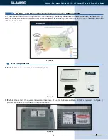
Page 4: ...ses of both LP N24 s involved In figure 8 you can see where to find them on the printed label LP N24 123 Manual for Installation in modes PTP and MTP II 1 Preparation For the configuration shown in fi...

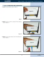
Page 5: ...ode Installation 5 Figure 9 II 2 1 Connect power as shown in figure 9 II 2 A Network LP N24 configuration Figure 10 Figure 11 II 2 2 Connect your PC to a LAN port of the LP N24 as shown in figure 10 I...

Page 6: ...d navigate to the default address of the Router 192 168 0 1 as shown in figure 14 II 2 7 A new window will pop up asking for the user and the password please use the defaults for User admin and passwo...

Page 7: ...ation window will pop up select option Next as shown in figure 16 II 2 9 Select option that corresponds to your Internet Service Provider ISP Most of them recommend Dynamic IP select Next as shown in...

Page 8: ...for reference purposes only if not please verify the cable connection from the LP N24 s WAN port to the ADSL modem or Internet service connection you can also try turning the ADSL Modem off and on aga...

Page 9: ...ield named Pass Phrase and select Apply as shown in figure 22 II 2 14 In this step we will stablish this equipment as a Repeater to do this select WLAN settings WDS Settings and in WDS Mode select Rep...

Page 10: ...IP addresseses to both networks Then Select Apply II 2 19 Now proceed to change the management password by selecting option System Tools Change Password input the new password in New Password then en...

Page 11: ...gh with the first part of the configuration This equipment must remain turned on for the second part of the configuration to take place which is explained in the following paragraphs Figure 30 Figure...

Page 12: ...re 34 Figure 34 II 3 5 Proceed to input the name of your WLAN by selecting option WLAN Settings Basic Settings and inputting in the field SSID the name you have selected for your WLAN in this example...

Page 13: ...the LP N24 of the B network In order to do this select Advanced Settings LAN Settings change the IP address to 192 168 0 2 because there should not be duplicate addresses when A and B get connected se...

Page 14: ...wn in figure 41 Figure 41 II 3 12 In this step we will disable the DHCP Server for this equipment this is so because the one that will assign the IP addresses in both networks is the LP N24 in network...

Page 15: ...case use TKIP as shown in figure 42 II 3 18 Proceed now to change the administration password by selecting option System Tools Change Password input in the new password in New Password and again in Re...

Page 16: ...ew paragraphs II 2 14 II 2 15 II 3 14 and II 3 15 In order to verify connections between both networks look for them and connect to each of them as shown in figure 31 If there is no success in anyone...

Reviews: