


HTCA-6400 User Manual
24
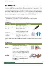
Processor Carrier
This is packed along with the processor. Before
performing any assembly involving this part,
please locate
PIN1
on one of the corners, an
important indicator used to align this carrier
with the processor and the bolster plate
correctly.
Dust Cover
This cover is used to protect the package land
surface of the processor from contamination.
To remove it from the processor, grasp the
holding features with your thumb and your
index finger while pulling the cover off
vertically.
Bolster Plate
A robust bolster plate is used to assist in PHM
alignment for installation, while effectively
helping eliminate PCB bowing during
compression. Please locate the
Cutout
on one
of the four corners before starting PHM
installation.
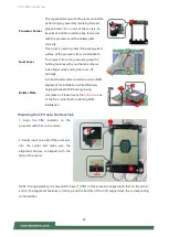
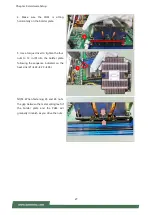
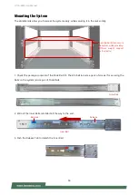
Mounting the CPU onto the Heat Sink
1. Align the PIN1 indicator on the
processor with that on the carrier.
2. Gently insert one side of the processor
into the carrier and make sure the
alignment feature is aligned with the
latch of the carrier.
NOTE: During assembly, it is essential to have (1) PIN1 on the processor aligned with that on the carrier,
and (2) the alignment features on the top and the bottom of the CPU aligned with the corresponding
carrier latches.
Latch
1
2
Cutout
Summary of Contents for HTCA-6400
Page 45: ...Chapter 4 BIOS Setup 45 Trusted Computing TPM 2 0...
Page 47: ...Chapter 4 BIOS Setup 47 Trusted Computing PTT Enable...
Page 49: ...Chapter 4 BIOS Setup 49 AST2500 Super IO Configuration...
Page 68: ...HTCA 6400 User Manual 68 Server ME Configuration...
Page 71: ...Chapter 4 BIOS Setup 71 Processor Configuration...