- 6 -
LANGER
EMV-Technik
DE-01728 Bannewitz
[email protected]
www.langer-emv.com
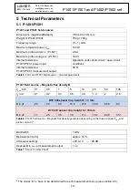
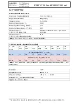
P1401/P1501 and P1402/P1502 set
No.
Name
Description
P1401 (P1401/P1501 set)
P1402 (P1402/P1502 set)
RF field source to generate a magnetic test field
P1501 (P1401/P1501 set)
P1502 (P1402/P1502 set)
RF field source to generate an electric test field
FKE 30
Field chamber insert (only for P1402 with D70 h10)
D70 h03
Spacer ring, 3 mm
D70 h10
Spacer ring, 10 mm
EPM 02
Field meter to measure the electric field
BPM 02
Field meter to measure the magnetic field
SMA-SMB 1 m
Measuring cable
Table 1
Brief description of the P1401/P1501 set; P1402/P1502 set
The following components, not included in the scope of delivery, are also needed:
ICE1 set, IC Test Environment
(Langer EMV-Technik GmbH)
-
GND 25
ground plane
-
GNDA 02
ground adapter
-
CB 0708
connection board
-
OA 4005
oscilloscope adapter
Measuring and test devices
-
Directional coupler
-
RF power amplifier
-
Signal generator
-
PC
-
Oscilloscope
-
Test IC monitoring equipment
Other
-
Test board for test IC
The test board together with the test IC is inserted into the ground plane of the measurement set-
up. The field source (here P1501) is located above the test IC by using a spacer ring. A signal
generator and an RF power amplifier are used to supply the field source. A directional coupler can
be used to monitor the forward power.
An oscilloscope and PC are needed to monitor the equipment under test and/or control the
measurement set-up. The voltage present on the electrode (P1501/P1502) and/or the current
flowing through the electric conductor (P1401/P1402) can be monitored via the field sources
’
measurement output.
The principal measurement process corresponds to IEC 62132-2:2010.


