


- 11 -
LANGER
EMV-Technik
DE-01728 Bannewitz
[email protected]
www.langer-emv.com
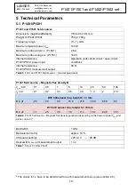
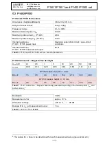
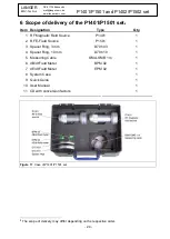
P1401/P1501 and P1402/P1502 set
Measurement outputs of the field sources
2.4
The field sources' measurement outputs can be used to calculate the magnetic flux density
B
or
electric field strength
E
generated by the field sources at the position of the test IC.
The voltage
u
out
has to be measured at the field sources
’ outputs for this purpose. The respective
field quantities can then be calculated using the conversion factors defined in
P1401/P1402
P1501/P1502
B = K1 ∙ i
P
i
P
= K4 ∙ u
out
E = K1 ∙ u
P
u
P
= K4 ∙ u
out
Table 2
Conversion factors of the field sources to calculate the field quantities
D70 h10 and D70 h03 spacer rings
2.5
The D70 h10 and D70 h03 spacer rings are part of the P1401/P1501 and P1402/P1502 IC test
systems. The spacer rings have an inner diameter d = 70 mm and a height h = 10 mm or
h = 3 mm. The spacer rings are used to position the field sources on the ground surface above the
test IC. The height of the spacer ring determines the distance between the field source and the IC.
The ground surface, the field source and the spacer ring form a field chamber in which the test field
develops.
Figure 9
D70 h03 and D70 h10 spacer rings
FKE 30 field chamber insert
2.6
The FKE 30 field chamber insert is only used together with the P1402 field source and the
D70 h10 spacer ring. When using the P1402 field source, the FKE 30 field chamber insert has to
be installed at the bottom of the field source as shown in
. The field source can then be
positioned on the spacer ring. The field chamber insert is now inside the spacer ring.
The field
chamber insert ensures a higher suppression of the field’s electric component.
Figure 10
FKE 30 field chamber insert for use with P1402 field source


