


- 21 -
LANGER
EMV-Technik
DE-01728 Bannewitz
[email protected]
www.langer-emv.com
P1401/P1501 and P1402/P1502 set
P1402/P1502
5.2
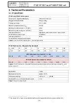
P1402 and P1502 field sources
Dimensions (height/width/depth)
(180 x 95 x 95) mm
Weight of P1401/P1501
750 g / 700 g
Frequency range
(0
– 3) GHz
Maximum forward power
𝑃
vor
100 W
Maximum probe current
𝑖
P
(P1401)
2.8 A
Maximum probe voltage
𝑢
P
(P1501)
140 V
Internal resistance,
P1401 / P1501 power input
Operation under short-circuit / open-circuit
conditions
Internal resistance,
P1401 / P1501 measurement output
50
Ω
Table 10
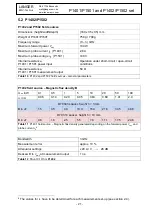
P1402 and P1502 field sources
– General parameters
P1402 field source
– Magnetic flux density B
𝑃
vor
in W
0.1
0.5
1
5
10
20
50
100
𝑖
P
in A
0.06
0.14
0.20
0.45
0.63
0.89
1.41
2.0
D70 h03 spacer, height h = 3 mm
B in µT
1.5
3.5
4.9
10.9
15.4
21.8
34.5
48.8
D70 h10 spacer, height h = 10 mm
B in µT
0.8
1.8
2.5
5.5
7.8
11.1
17.5
24.8
Table 11
P1401 field source
– Magnetic flux density generated depending on the forward power
𝑃
vor
and
probe current
𝑖
P
6
Bandwidth
3 GHz
Measurement error
approx. 10 %
Attenuator settings
x 20 A / V
→ 26 dB
Deskew B to
𝑣
out
at measurement output
1 ns
Table 12
Shunt 0.1 Ohm
P1402
6
The values for
𝑖
P
have to be determined for each measurement set-up (see section 2.4).


