


17
Troubleshooting
Symptoms & Possible Causes
The following are charts of Symptoms and Possible Causes to aid in diagnosing faults with your unit.
Refer to the symptoms column to locate the type of failure then to the Possible Cause for the items to be checked.
To test for a possible cause refer to test to identify test procedures. Test indicated with an “*” should be done by a
Lang factory authorized service representative.
NOTICE
If an item on the list is followed by an asterisk (*), the work should be done by
a Lang factory authorized service representative.
USE OF ANY REPLACEMENT PARTS OTHER THAN THOSE SUPPLIED BY
LANG OR THEIR AUTHORIZED DISTRIBUTORS CAN CAUSE BODILY INJURY
TO THE OPERATOR AND DAMAGE TO THE EQUIPMENT AND WILL VOID ALL
WARRANTIES.
NOTICE
Service on this or any other Lang appliance must be performed by qualified
personnel only. Consult your Lang Authorized Service Agent Directory. You
can call our toll free number 314-678-6315 or visit our website
WWW.LANGWORLD.COM for the service agent nearest you.
BOTH HIGH AND LOW VOLTAGES ARE PRESENT INSIDE THIS APPLIANCE
WHEN THE UNIT IS PLUGGED/WIRED INTO A LIVE RECEPTACLE. BEFORE
REPLACING ANY PARTS, DISCONNECT THE UNIT FROM THE ELECTRIC
POWER SUPPLY.
CAUTION
WARNING
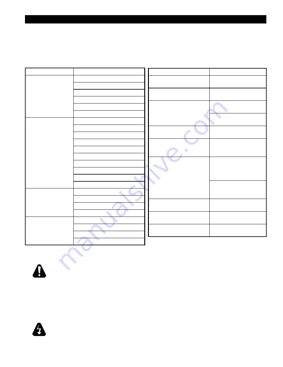
SYMPTOM
POSSIBLE CAUSE
Power indicator is not lit.
No power to cord outlet
Oven unplugged from outlet
Failed power cord or plug
Failed power switch
Failed indicator light
Failed pilot ignition
Oven will not heat
Power Switch is not “ON”
Failed Pilot ignition
Failed 12-position switch
Failed Circuit Board
Failed Probe
Failed Contactor
Failed Centrifugal switch in Motor
Failed Motor
Failed Over-temperature Thermostat
Failed Valve
Product burning
Product is cooked too long
Failed 12-position switch
Failed circuit board
Failed probe
Product under done
Product is not cooking long enough
Failed 12-position switch
Failed circuit board
Failed probe
Possible Cause
TEST
Product is cooked too long
No test available, operational
condition
Failed Probe
Check probe for proper
resistance*
Failed Circuit Board
Confirm that board is getting
correct voltage*
Confirm that board is putting
out correct voltage*
Failed Valve
Remove the wires and check
for continuity across the coil*
Failed Centrifugal switch in Motor Remove the wires and check
for continuity across them
while motor is turning*
Failed Motor contactor
Remove the wires from the
contactor coil and check for
continuity across the contactor
coil connection*
Ensure the contactor
moveable points move freely
up and down*
Failed Motor
Confirm that motor is getting
correct voltage*
Failed or disconnected safety
thermostat
Check across the thermostat
connectors for continuity*
Failed Spark Module
Confirm that Spark Module is
getting proper voltage*