background image

9

INSTALLATION CONT’D

COUNTER TOP

Split the back into two pieces.

Remove the screws from the rear of the cheese-melter; screw the stainless steel portion

of the back to the cheese-melter with the offset at the top.

Reinstall the two back halves together and replace the screws around the edge.

When installing on a counter the legs must be installed before using the unit, as they

will provide the required clearance for the bottom of the unit.

Place the unit in location, and level using leg adjustments.

Observe minimum clearances at all times.

ELECTRICAL

Electrical service routing may be made through either of two 1 1/4-inch knockouts

provided. One may be found along the bottom edge of the back panel. The second

knockout is located on the bottom of the unit.

Reference the Data Plate on the left side of the unit for amperage, voltage and phase

requirements. Insure that the power supply is sufficient to meet the units power needs.

Check your local or national electrical code for fuse or circuit breaker requirements.

PHASING

All model numbers 124CM and 136CM are shipped single phase.

148CM is shipped three-phase and can be converted to single phase by moving wire #3

to L1.

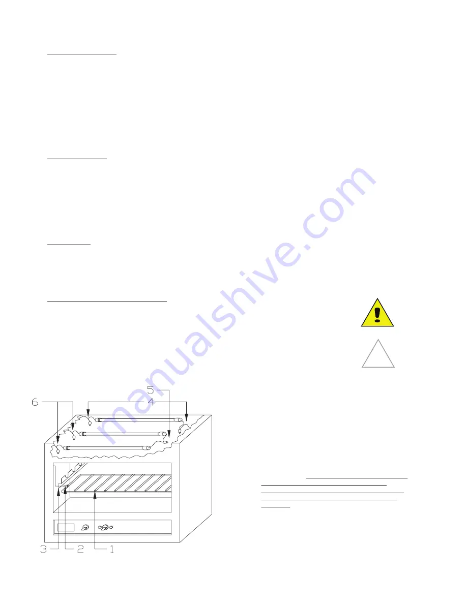
ELEMENT REPLACEMENT

CAUTION: ALWAYS KEEP THE AREA NEAR THE APPLIANCE

FREE FROM COMBUSTIBLE MATERIALS.

NOTICE:

The electric cheese melter must be installed more

than 12 inches above any cooking surface and never

above any open burners or charbroilers.

1.

Disconnect from power and remove shelf.

2.

Remove three screws from each heater bracket.

3.

Remove brackets.

4.

Install the rear quartz heater (white end caps) to 

the power leads on both rear sides of the unit 

using the ceramic wire nuts provided.

5.

The middle and front quartz heaters (red or 

brown end caps) are wired together (in series) 

using the ceramic wire nuts provided.

6.

The middle and front quartz heaters are each 

connected to a power lead using the ceramic wire 

nuts provided. On 124 and 136 units, this connec-

tion will be on the left. On 148 units, these 

connections will be on the left for the left set of 

elements, and on the right for the right set of 

elements.

7.

Replace brackets removed in step 3.

8.

Replace shelf removed in step 1.

9.

Reconnect to power. Turn power on and check for 

proper operation

SK3182 REV - (07-23)

Summary of Contents for 124CMW

Page 1: ...le in kitchens for restaurants canteens hospitals and in commercial enterprises such as bakeries butcheries etc but not for continuous mass production of food ELECTRIC CHEESEMELTER 124CMW 136CMW 148CM...

Page 2: ...LS GAS THIS INFORMATION SHALL BE OBTAINED BY CONSULTING YOUR LOCAL GAS SUPPLIER AS A MINIMUM TURN OFF THE GAS AND CALL YOUR GAS COMPANY AND YOUR AUTHORIZED SERVICE AGENT EVACUATE ALL PERSONNEL FROM TH...

Page 3: ...APTER PAGE TABLE OF CONTENTS 3 READ FIRST 4 EQUIPMENT DESCRIPTION 6 UNPACKING 7 INSTALLATION 8 OPERATION 11 MAINTENANCE CLEANING PROCEDURES 13 TROUBLESHOOTING 14 WIRING DIAGRAMS 16 17 EXPLODED VIEWS 1...

Page 4: ...APPLICABLE CODES NOTICE The data plate is located on the left side of unit towards the front The melter voltage wattage serial number wire size and clearance specifications are on the data plate This...

Page 5: ...han 10 minutes Longer contact can cause corrosion NOTICE Service on this or any other LANG appliance must be performed by qualified personnel only Consult your authorized service agent directory or ca...

Page 6: ...and reduced heat loss Interior Construction The interior dimension are 9 5 24cm High 14 5 37cm Deep 21 25 32 45 25 54cm 81 25cm 115cm wide dependent on the actual model number The interior of the mel...

Page 7: ...move the melter as near to its intended location as practical The crating will help protect the unit from the physical damage normally associated with moving it through hallways and doorways Un cratin...

Page 8: ...m to their applicable National State and locally recognized installation standards INSTALLATION WALL MOUNT UNITS The unit back is not attached to the machine It is packaged loose behind the cheese mel...

Page 9: ...ING All model numbers 124CM and 136CM are shipped single phase 148CM is shipped three phase and can be converted to single phase by moving wire 3 to L1 ELEMENT REPLACEMENT CAUTION ALWAYS KEEP THE AREA...

Page 10: ...04V OR 120V ELEMENT 104V OR 120V ELEMENT 208V OR 240V ELEMENT CONNECT BLUE RED BLUE CONNECT CONNECT CONNECT 208V OR 240V ELEMENT 104V OR 120V ELEMENT 104V OR 120V ELEMENT 208V OR 240V ELEMENT 104V OR...

Page 11: ...ide the rack in and out of the slots provided Make sure that the end of the rack engages the sliding mechanism located on the right front corner CONTROLS Controls are located on the front panel and co...

Page 12: ...rcuit the rear element appears dimly lighted and the front elements appear not energized In the AUTOMATIC mode the elements are activated to provide full heat only when product is placed on the rack P...

Page 13: ...less steel surfaces longer than 10 minutes Longer contact can cause corrosion Cleaning Always start with a cold melter The stainless exterior can easily be cleaned using warm water and mild detergent...

Page 14: ...IS PLUGGED WIRED INTO A LIVE RECEPTACLE BEFORE REPLACING ANY PARTS DISCONNECT THE UNIT FROM THE ELECTRIC POWER SUPPLY HIGH VOLTAGE Possible Cause TEST Incorrect Voltage Confirm that voltage is correct...

Page 15: ...REV BY REV DATE DLG 14 6 3 WIRE NUT 4 NUT WIRE NUT WIRE NUT WIRE 5 17 17 QUARTZ HEATER NUT WIRE HEAT SWITCH PILOT LAMP CONSTANT PILOT LAMP NUT WIRE 12 16 15 POWER SWITCH 9 13 10 11 CONTACTOR MICRO NC...

Page 16: ...1 12 9 13 LEFT PILOT LAMP LAMP BOTH PILOT 30 25 21 WIRE NUT NUT WIRE 26 SWITCH SIDE 22 23 27 30 30 NUT WIRE PILOT LAMP AUTOMATIC 24 5 CONTACTOR 20 18 4 16 17 16 3 QUARTZ HEATER HEAT SWITCH PILOT LAMP...

Page 17: ...17 1 2 3 4 1 5 6 1 7 20 19 17 See Detail A 9 12 18 13 14 15 16 8 8 9 10 11 1 1 1 1 1 1 21 22 30 31 SK2246 Rev 5 2 07 Model 124CM Electric Cheesmelter...

Page 18: ...18 23 25 24 26 11 9 27 28 29 SK2247 Rev 5 2 07 Model 124CM Electric Cheesmelter Control Panel Assembly 26 3 Pole 2 Pole Detail A...

Page 19: ...C 20101 24 16 SCRW MS PLT 10 32 X 375 ALL 10 2C 20202 07 4 WSHR LOCK 10 STD SPLIT ALL 11 2C 20301 15 4 NUT HEX 10 32 PLTD ALL 12 2B 50200 13 1 RACK MELTER 24 ALL 13 J9 MM 167 1 1 RACK SLIDE WELDMENT 5...

Page 20: ...LL 9 2C 20101 24 16 SCRW MS PLT 10 32 X 375 ALL 10 2C 20202 07 4 WSHR LOCK 10 STD SPLIT ALL 11 2C 20301 15 4 NUT HEX 10 32 PLTD ALL 12 2B 50200 14 1 RACK MELTER 36 ALL 13 J9 MM 167 1 1 RACK SLIDE WELD...

Page 21: ...MS PLT 10 32 X 375 ALL 10 2C 20202 07 4 WSHR LOCK 10 STD SPLIT ALL 11 2C 20301 15 4 NUT HEX 10 32 PLTD ALL 12 2B 50200 15 1 RACK MELTER 48 ALL 13 J9 MM 167 1 1 RACK SLIDE WELDMENT 5 16 ALL 14 2C 2010...

Page 22: ...ld against the bottom of the cheesemelter with the opening at the back of the unit and align the screw holes Thread four 4 cap screws through the heat shield and into the cheesemelter Using a wrench t...

Page 23: ...d com PRODUCTS PARTS LABOR Lang Strato Series convection ovens 2 years 2 years Lang convection oven doors excluding hardware lifetime 2 years Lang griddles 2 years 2 years Chrome griddle surfaces agai...

Page 24: ...STAR MANUFACTURING INTERNATIONAL INC Star Holman Lang Wells Toastmaster 265 HOBSON ST SMITHVILLE TN 37166 800 264 7827 www star mfg com...

Reviews: