


MAINTENANCE AND LUBRICATION
4-11
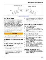
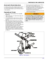
Figure 4-7: Brake Lining Wear
Spring Air Brake
Check for faulty units. Check the condensation holes on
the underside of the brake chambers to make sure they
are open. The spring brake has two brake chambers, a
service chamber and an emergency chamber or spring
chamber. Service brake chambers should be
disassembled and cleaned at 50,000 miles or yearly. The
diaphragm and any marginal parts should be replaced.
When replacing the service diaphragm, replace the
corresponding parts for the other chamber on the same
axle (to aid in even brake application and release).
Examine yoke pin for wear and replace as necessary.
The spring chamber should not be serviced. Replace
entire unit (both service and spring chamber) if spring
chamber becomes faulty.
WARNING
Replacing the Spring Air Brake
Unit
Caging the Power Spring in the
Spring Chamber
1.
Chock the trailer wheels.
2.
Remove dust cap from the rear of the spring brake
chamber
3.
Remove the release bolt from it’s holding brackets.
Insert it into the spring brake chamber until it can be
rotated and hooked into place.
DO NOT USE AN
IMPACT WRENCH TO CAGE THE SPRING
BRAKE!
4.
Turn the nut on the release bolt until the spring brake
is caged. This should be 2-1/4 to 2-1/2 inches of
release bolt extension.
5.
The brakes should now be released. Do not operate
loaded trailer with brake manually released.
Uncaging the Power Spring in
the Spring Chamber
1.
Chock the trailer wheels.
2.
Turn the nut on the release bolt until the spring is
released. Remove the release bolt and store it in its
brackets.
3.
Snap the dust cap back in place on the chamber.
Removal of Brake Unit
1.
Chock all tractor and trailer wheels and drain the air
system.
2.
Mark the brake chamber for proper air line port
alignment for reassembly.
3.
CAGE THE POWER SPRING following the steps
outlined in
“Caging the Power Spring in the Spring
4.
Disconnect the slack adjuster from the connecting
rod by removing the clevis pin
5.
Mark all air service lines for proper re-installation and
disconnect from the brake chamber.
6.
Remove the brake chamber from the axle brackets.
Installation of Brake Unit
1.
CAGE THE POWER SPRING following the steps
outlined in
“Caging the Power Spring in the Spring
The spring brake chamber employs a spring with
high forces. Service should not be attempted.
Serious injury or death may result.
Summary of Contents for 345F
Page 2: ......
Page 6: ......
Page 22: ...3 10 F 944 1017 Edition OPERATING INSTRUCTIONS Figure 3 4 Steps for Loading and Unloading...
Page 30: ...3 18 F 944 1017 Edition OPERATING INSTRUCTIONS Page Intentionally Blank...
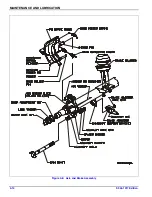
Page 44: ...4 14 F 944 1017 Edition MAINTENANCE AND LUBRICATION Figure 4 8 Axle and Brake Assembly...
Page 61: ......


