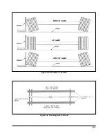
b. Straight Edge or String Method
: (This
method cannot be used if tire and wheel as-
semblies are not mounted on the axle.) Jack
trailer up until the wheels are off of the
ground. Hold a straight edge against the tires
of both ends of an axle. A gap at one tire indi-
cates a smaller tire. A maximum of 1/8" gap is
allowed
(See Figure 4-17)
.
4-11.3
Mounting Tire and Wheel (Hub Type)
a.
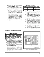
Make sure that all mounting surfaces are
clean and free of rust, dirt or paint. A wire
brush may be used to clean these surfaces
(See Figure 4-18)
.
b.
Position the inner disc wheel over the studs,
being careful not to damage the stud threads.
Make sure that the disc wheel is flat against
the mounting surface and that there is clear-
ance between the disc wheel taper and brake
drum.
c.
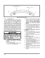
For ball seat mounted wheels only, install
the inner capnuts on the studs and tighten to
fifty foot-pounds using the sequence illus-
trated in
Figure 4-19
. Make certain that the
left-handed threads are installed on the driver
side of the vehicle and the right-handed
threads are installed on the curbside of the
vehicle.
d.
Tighten the inner capnuts to full torque of
450 to 500 foot-pounds using the sequence
shown in
Figure 4-19
e.
For pilot mounted wheels, skip steps c and
d.
f.
Position the outer disc wheel over the
capnuts being careful not to damage the inner
capnut threads. Be sure the valve stems for
both the inner and outer tire are accessible.
g.
Install the outer capnuts (ball seat) or flange
nut (pilot mount) and tighten to 50 foot-
pounds using the sequence in
Figure 4-19.
Then tighten to full torque of 450 to 500 foot-
pounds for ball seat and 500 to 550 foot-
pounds for pilot mount, using the same se-
quence
.
h.
Torque will drop after the first 50 to 100
miles of operation. Check the capnuts for
proper torque after this interval and retighten
them. Loosen the outer capnuts and retighten
the inner and outer capnuts per
steps d to g.
WARNING
USE A TORQUE WRENCH TO ASSURE
PROPER TORQUE. INSUFFICIENT
TORQUE CAN CAUSE STUD BREAK-
AGE AND DAMAGE WHEEL PILOTS.
OVERTORQUE CAN OVERSTRESS
THE STUDS AND STRIP THE
THREADS.
4-11.4
Mounting Tire and Rim (Spoke Type
)
a.
Slide the inside rim over the wheel so the
28
o
mounting surfaces mate. Be sure the
valve stem is pointing out and is centered be-
tween two spokes.
b.
Slide the rim spacer over the wheel and
against the inner rim. If the spacer is dam-
aged, replace with a new spacer.
c.
Slide the outer rim over the wheel. Be sure
the valve stem is pointing in and is centered
between the same spokes as the inner valve
stem.
d.
Install the rim clamp and nuts. Lightly
tighten the rim nuts until they are properly
seated.
e.
After they are properly seated, tighten the
rim nuts one-quarter turn at a time, in the or-
der illustrated in
Figure 4-19
to a torque of
200 to 250 foot-pounds.
f.
Check your rim alignment by placing a block
of wood or other object on the floor and rotat-
ing the wheel. If the variation exceeds 1/16"
for the front wheels or 1/8" for the rear
wheels, the rim is not properly mounted. To
correct the problem, loosen the nut on the
side with the greatest deviation and tighten
the nuts opposite to this nut. Recheck the
torque.
g.
Check space between dual wheels. Side
walls should not be in contact.
h.
Torque will drop after the first 50 to 100
miles of operation. Check the capnuts or
flange nuts for proper torque after this interval
and retighten them.
4-25
Summary of Contents for 345B
Page 3: ...MODEL 345B TRAILER OPERATOR S MANUAL PURCHASED FROM DATE ADDRESS PHONE NO SERIAL NO ...
Page 8: ......
Page 12: ......
Page 22: ...3 10 Figure 3 4 Steps for Loading and Unloading ...
Page 26: ...3 14 Figure 3 7 Rear Impact Guard and Antilock Brake System ...
Page 30: ......
Page 35: ...4 5 Figure 4 2 345B Wiring Diagram ...
Page 36: ...4 6 Figure 4 3 Remote Wiring Diagram ...
Page 41: ...4 11 Figure 4 5 Examples of Camber Figure 4 6 Checking Axle for Bend ...
Page 46: ...4 16 Figure 4 10 Axle and Brake Assembly ...
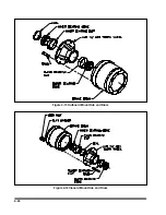
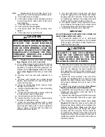
Page 50: ...4 20 Figure 4 13 Outboard Mount Hub and Drum Figure 4 14 Inboard Mount Hub and Drum ...
Page 54: ...4 24 Figure 4 18 Mounting Tires and Wheels Figure 4 19 Stud Tightening Sequence ...
Page 65: ...5 9 NOTES ...

