Section 2: Tractor Hook-up & Unhook
SBD3596 & SBD35108 Snow Blowers 370-347M
4/9/21
20
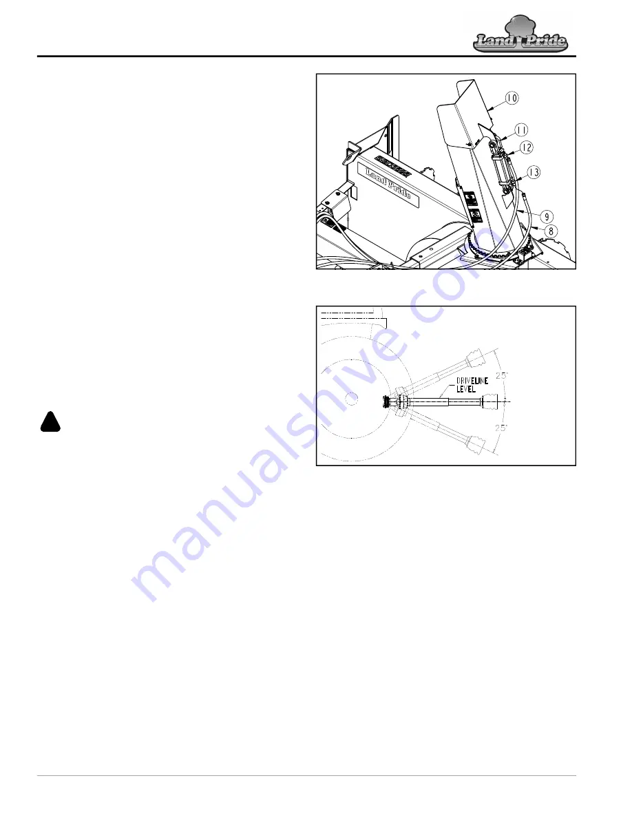
Refer to Figure 2-9:
2. Set tractor control lever in the non-float position.
3. It is best if chute deflector (#10) adjusts up when
pushing control lever on the tractor forward. If
deflector does not adjust in the direction desired,
switch quick disconnect couplings at the duplex
outlet.
4. Cycle hydraulic system by extending and retracting
cylinder (#11) several times to purge it of air.
5. Purge hydraulic system if hydraulic cylinder operates
unevenly after cycling it several times:
a. Loosen elbow fitting (#12) at the rod end of the
hydraulic cylinder.
b. Slowly retract and extend hydraulic cylinder until
all trapped air is purged from the cylinder and
hose.
c. Tighten elbow fitting (#12).
d. Loosen elbow fitting (#13) at the base end of
hydraulic cylinder (#11).
e. Slowly retract and extend hydraulic cylinder (#11)
until all trapped air is purged from the cylinder and
hydraulic hoses.
f. Tighten elbow fitting (#13).
Check Driveline Interference
Refer to Figure 2-10:
WARNING
!
To avoid serious injury or death:
A rotating driveline must not exceed an angle of 25 degrees up
or down, and never engage a driveline while at an angle
exceeding 25 degrees up or down. The driveline can break and
1. Start tractor and raise implement slightly off the
support blocks used to install the driveline. Drive
forward until the implement is clear of the supports.
2. Slowly and carefully lower and raise the implement to
ensure drawbar, tires, and other equipment on the
tractor do not contact the implement’s frame. If there
is an interference:
a. Back implement over the support blocks and
lower it onto the blocks.
b. Shut tractor down before dismounting. Refer to
c. Move or remove drawbar if it interferes with the
implement and make any other necessary
corrections.
d. Repeat steps 1-2 to verify the implement does not
interfere with the tractor.
3. Start tractor, raise implement fully up. Back
implement over the support blocks. Do not lower
implement onto the support blocks.
4. Without changing the 3-point lift height, shut tractor
down using
.
Purge Chute Hydraulic Cylinder
Figure 2-9
Maximum Driveline Movement During Operation
Figure 2-10
5. Check to make sure driveline does not exceed any of
the limits listed below:
•
Driveline does not exceed maximum length
recorded in step 3 under
•
Driveline angle does not exceed 25
o
above
horizontal.
6. If driveline exceeds maximum allowable length or 25
degrees up:
a. Adjust tractor 3-point lift limiter to the height that
will keep the driveline within the recommended
limits.
b. If the 3-point left lever does not have a lift height
limiter, make a mark with tape or other means to
indicate maximum lift height.
7.
Start tractor, raise implement slightly, and drive
forward enough to clear the support blocks.
8. Lower implement to the ground and shut tractor down
using
24872


