
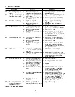


4. TROUBLESHOOTING
TROUBLE
CAUSE
REMEDY
4.1
Water leakage around
A. Damaged or improperly
A. If damaged, replace. If improperly
nozzle.
installed o-ring above diffuser.
installed, adjust.
4.2
Leakage between upper A. Gap between upper and lower A. Tighten all six (6) retaining screws.
and lower valve bodies.
valve bodies.
B. Worn or damaged paddle arm B. Replace paddle arm assemblies.
assemblies.
4.3
Miscellaneous leakage.
A. Gap between parts.
A. Tighten appropriate retaining
screws.
B. Damaged or improperly
B. Replace or adjust appropriate
installed o-rings.
o-rings.
4.4
Insufficient water flow.
A. Insufficient incoming supply
A. Verify incoming supply water
water pressure.
pressure is a minimum of 25 PSI.
B. Shutoff on mounting block
B. Open shutoff fully.
not fully open.
C. Foreign debris in water flow
C. Remove water flow control from
control.
upper body and clean out any
foreign material to ensure smooth
free spool movement.
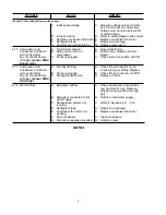
4.5
Insufficient syrup flow.
A. Insufficient CO
2
pressure to
A. Adjust CO
2
pressure to 80 PSI
BIB pumps.
(minimum 70 PSI) for BIB pumps.
B. Shutoff on mounting block
B. Open shutoff fully.
not fully open.
C. Foreign debris in syrup flow
C. Remove syrup flow control from
control.
upper body and clean out any
foreign material to ensure smooth
free spool movement.
4.6
Erratic ratio.
A. Incoming water and/or syrup
A. Check pressure and adjust.
supply not at minimum flowing
pressure.
B. Foreign debris in water and/or B. Remove syrup flow controls from
syrup flow controls.
upper body and remove any foreign
material to ensure smooth free
spool movement.
4.7
No product dispensed.
A. Water and syrup shutoffs on
A. Open shutoffs fully.
mounting block not fully open.
B. The key switch on an electric
B. Turn key switch to ON position.
valve is in the OFF position.
C. Cup lever arm or ID panel
C. Repair.
actuator on electric valve is
not actuating the switch.
D. Electric current not reaching
D. Check electric current supplied
valve.
to valve. If current is adequate,
check solenoid coil and switch,
and replace if necessary.
E. Improper or inadequate water
E. Remove valve from mounting
or syrup supply.
block and open shutoffs slightly and
check water and syrup supply. If
no supply, check dispenser for
freeze-up or other problems.
F. Blown fuse on 24 volt
F. Find cause of short and correct.
transformer.
Then replace transformer.
4.8
Water only dispensed;
A. Water or syrup shutoff on
A. Open shutoff fully.
no syrup; or syrup only
mounting block not fully open.
dispensed; no water.
(Section 4.8 continued on next page.)
5


