background image

SPECIFICATIONS

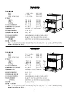
1500 POSTMIX

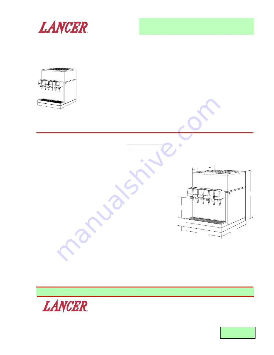
DIMENSIONS

Width

19 3/16 inches

(48.74 cm)

Depth

24 inches

(60.96 cm)

Height (without legs)

25 3/8 inches

(64.45 cm)

WEIGHT

Shipping

150 pounds

(68.2 kg)

Empty

130 pounds

(59.0 kg)

Operating

220 pounds

(99.8 kg)

ICE BANK WEIGHT

30 pounds

(13.6 kg)

WATER BATH CAPACITY

12 gallons

(45.4 liters)

COMPRESSOR

1/3 HP, Tecumseh, 115V/60Hz

AGITATOR MOTOR

25 W, 115V

CONDENSER MOTOR

9 W, 115V

ICE BANK CONTROL

Lancer Electronic Ice Bank Control (EIBC)

TRANSFORMER

Basler, 115V (Primary)/24V (Secondary)

OPTIONS

230V/50Hz and 240V/60Hz systems available

DRINK CAPACITY

395 - 12 ounce (354.8 ml) drinks under 40°F (4.4°C) at four (4) drinks per minute with 75°F (23.9°C)
ambient inlet water and syrup.

INSTALLATION AND SERVICE MANUAL

FOR LANCER DISPENSERS

SERIES 1500 POSTMIX

SERIES 1500E POSTMIX

SERIES 1500 PREMIX

REV.

02/11/00

P.N.

28-0450

This is an initial manual release.

FAX ENGINEERING: • 210-310-7096

"Lancer" is the registered trademark of Lancer • Copyright — 2000 by Lancer, all rights reserved.

25 3/8 "

64.45 cm

18 3/4 "

47.63 cm

24 "

60.96 cm

19 3/16 "

48.74 cm

9 1/2 "

24.13 cm

3 1/2 "

8.89 cm

Please refer to the Lancer web site (

www.lancercorp.com

) for

information relating to Lancer Installation and Service Manuals,
Instruction Sheets, Technical Bulletins, Service Bulletins, etc.

6655 LANCER BLVD. • SAN ANTONIO, TEXAS 78219 USA • (210) 310-7000

FAX SALES

• NORTH AMERICA – 210-310-7245 • INTERNATIONAL SALES – 210-310-7242 • CUSTOMER SERVICE – 210-310-7242 •

• LATIN AMERICA – 210-310-7245 • EUROPE – 32-2-755-2399 • PACIFIC – 61-8-8268-1978 •

Summary of Contents for SERIES 1500 POSTMIX

Page 1: ...75 F 23 9 C ambient inlet water and syrup INSTALLATION AND SERVICE MANUAL FOR LANCER DISPENSERS SERIES 1500 POSTMIX SERIES 1500E POSTMIX SERIES 1500 PREMIX REV 02 11 00 P N 28 0450 This is an initial...

Page 2: ...up SPECIFICATION 1500 PREMIX DIMENSIONS Width 19 3 16 inches 48 74 cm Depth 24 inches 60 96 cm Height without legs 25 3 8 inches 64 45 cm WEIGHT Shipping 150 pounds 68 2 kg Empty 130 pounds 59 kg Oper...

Page 3: ...WILL NOT SHUT OFF 6 4 10 EXCESSIVE FOAMING 6 4 11 COMPRESSOR DOES NOT START NO HUM BUT CONDENSER FAN MOTOR RUNS 6 4 12 COMPRESSOR STARTS AND CONTINUES TO RUN UNTIL FREEZE UP AND WILL NOT CUT OFF 6 4 1...

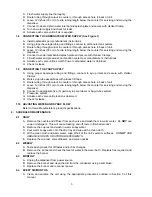
Page 4: ...o sit on a flat supported surface capable of supporting a minimum weight of 400 pounds 182 kg It may be either counter or leg mounted A template is provided to cut and or drill the necessary holes for...

Page 5: ...e installation Approximately three 3 hours are required to form a full ice bank NOTE Units equipped with an electronic ice bank control contain a five 5 minute delay Compressor and fan motor will not...

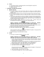
Page 6: ...te tubing through cutout in counter or through access hole in back of unit D Leave 12 inches 30 cm of extra tubing length below the counter for servicing and moving the dispenser E Connect to appropri...

Page 7: ...t 50 PPM 50 mg L chlorine Make sure that lines are completely filled and allow to stand for 10 minutes G Reconnect syrup containers and ready Unit for operation H Draw drinks to refill lines and flush...

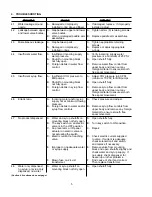
Page 8: ...ve syrup flow control from control upper body and clean out any foreign material to ensure smooth free spool movement 4 6 Erratic ratio A Incoming water and or syrup A Check pressure and adjust supply...

Page 9: ...rated voltage C Incorrect wiring C Refer to wiring diagram and correct D Compressor malfunctioning D Replace compressor 4 12 Compressor starts and A Ice bank control failure A Replace ice bank control...

Page 10: ...tion at PCB Off delay Lancer EIBC Export only 4 17 Compressor and A Improper Wiring A Check Power Indicator Lamp Condenser Fan Motor check wiring per Wiring Diagram will not start after B Probe unplug...

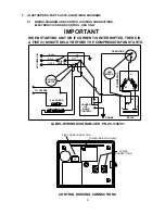
Page 11: ...OTOR WHITE BLACK GREEN KILL SWITCH JCT COMPRESSOR LANCER ICE BANK CONTROL PROBE L RELAY S M M S FAN MOTOR C OVERLOAD WHEN STARTING UNIT OR IF CURRENT IS INTERRUPTED THERE IS A FIVE 5 MINUTE DELAY BEFO...

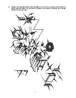
Page 12: ...19 TO 42 TO 18 18 TO 11 28G 17 43 23 9 44 15 30 41 29G 29 32 TO 4 TO 18 5 22 40 40A 40B 12 11 14 13 20 45 31 7 8 10 21 42 24 33 34 35 36 46 47 TO KEYLOCK TO VALVES TO TRANSFORMER LOAD TO TRANSFORMER L...

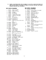
Page 13: ...0433 01 Label 115V 60Hz 9W 28G 04 0059 Screw 8 36 x 0 375 29 52 1259 Agitator Motor Assy 115V 60Hz 25W 29A 91 0084 Motor Agitator 115V 60Hz 25W 29B 02 0032 Washer Rubber 1 0 Inch OD 29C 06 0633 Label...

Page 14: ...LL HOLE IMPOR TANT FILL WATER BATH UNTIL TANK OVERF LOW TUBE WATER FLOWS FROM TO TRANSFORMER LOAD TO COMPRESSOR TO TRANSFORMER LINE TO VALVES TO KEYLOCK 39 6 3 37 25 4 37 38 1 5 26 T O 3 2 2 TO 18 28A...

Page 15: ...0059 Screw 8 36 x 0 375 29 52 1259 Agitator Motor Assy 115V 60Hz 52 1379 Agitator Motor Assy 220 240V 50 60Hz 29A 91 0086 Motor Agitator 220V 50 60Hz 91 0084 Motor Agitator 115V 60Hz 29B 02 0032 Wash...

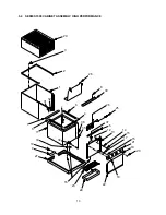
Page 16: ...3 29 2 1 32 31 7 6 11 8 9 10 27 16 33 34 23 24 22 18 20 19 21 13 15 17 15 14 12 5 37 25 26 36 35 4 6 30 28 8 5 4 SERIES 1500 CABINET ASSEMBLY HIGH PERFORMANCE 13...

Page 17: ...Housing 21 23 0389 Faucet Plate 6V 23 0394 Faucet Plate 5V 23 0771 Faucet Plate 4V 22 30 6644 Splash Plate without Logo 30 6644 01 Splash Plate with Logo 23 23 0159 Cup Rest 24 54 0017 Drip Tray 25 1...

Page 18: ...27 23 5 4 6 4 7 2 32 12 33 34 35 22 1 24 12 12 30 31 12 20 19 12 13 11 26 21 3 28 11 8 29 14 17 18 16 15 14 10 9 25 6 5 5 SERIES 1500E AND 1500 PREMIX CABINET ASSEMBLY 15...

Page 19: ...30 6644 01 Splash Plate with Logo 19 23 0159 Cup Rest 20 54 0017 Drip Tray 21 12 0097 Key Lock Switch 22 52 0891 Harness Assy 6V 52 0890 Harness Assy 5V 52 0889 Harness Assy 4V 23 23 0831 Insulator P...

Page 20: ...17 NOTES Please refer to the Lancer web site www lancercorp com for information relating to Lancer Installation and Service Manuals Instruction Sheets Technical Bulletins Service Bulletins etc...

Reviews: