background image

5

A. Regulator Adjustment Screw

B. Adjust to 110 PSI (0.758 MPA)

C. Wrench

A

B

C

8.  Adjust both of the low pressure regulators on the regulator 

manifold to 75 PSI (0.517 MPA) then tighten locknut with 

wrench.  

9.  Activate each valve until gas-out.
10.  Plug in the remote carbonator pump deck, if not already 

done so, and turn the switch to the ON position.

11.  Activate each valve until the carbonator pump comes on.  

Release the button, allow carbonator to fill and stop.  

Repeat this process until a steady flow of carbonated water 

is achieved.

12.  Activate each valve to purge air from the syrup lines. 


The pump deck has a 3 minute timeout feature. If the


timeout occurs, turn the deck OFF then ON by flipping


the switch on the control box.

NOTE


To check for CO

2

 leaks, close the valve on the CO

2


cylinder and observe if the pressure to the system 


drops with the  cylinder valve closed for five minutes. 


Open the cylinder valve after check.

NOTE

5.  Activate each valve to ensure a good flow of water is 

achieved. 

6.  Ensure pump deck is turned OFF before turning on CO

2

7.  Turn on CO

2

 at the source then, using a screwdriver, adjust 

the high pressure regulator at the source to 110 PSI (0.758 

MPA) then tighten locknut with wrench. 

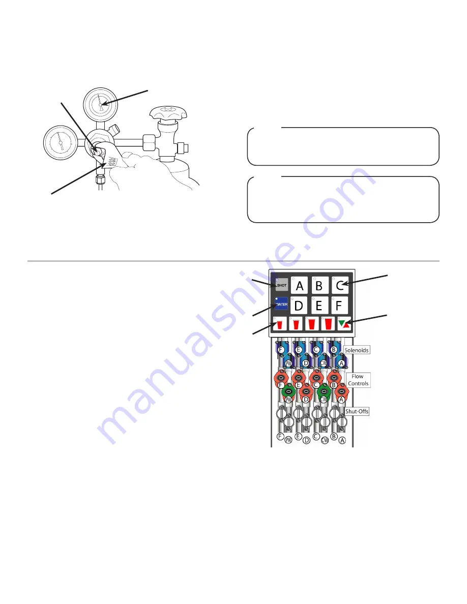
MULTI-VALVE UNIT (MVU) PROGRAMMING

Overview

The MVU module is designed to dispense up to 6 beverages and/

or shots through one dispense nozzle. The MVU consists of: an 

electronic board, touch pad which is used to both program and

dispense drinks, 8 solenoids (one for each circuit), 8 flow controls 

(one for each circuit), and 8 shut-offs
1.  Positions A and D are plumbed through the cold plate  

meaning that the syrup is chilled in each of those locations. 

2.  Positions B, C, E, and F bypass the cold plate so the syrups 

are not chilled and should 

NOT

 be used for carbonated 

beverages.

3.  The water flow controls are green in color the plain water 

control is labeled with “PW”, and the carbonated water is 

labeled with “CW”. There are no stickers on the water flow 

controls.

4.  The syrup flow control modules are red and correspond to 

the touch pad, (touchpad position A activates solenoid A).

5.  The 8 solenoids are 24 VDC, activated by the touch pad, and 

controlled by the MVU circuit board.

A. Brand Button

B. Shot Button

C. Water Button

D. Portion Control  

    Buttons

E. Pour/Cancel

A

E

B

C

D

Summary of Contents for Multi-Valve Unit Tower

Page 1: ...for the unit being installed is required or needed please refer to the Lancer web site lancercorp com for immediate access or for your convenience scan this QR code with a mobile device app required...

Page 2: ...25 inches 184 15 mm Depth 9 inches 228 6 mm Height 16 5 inches 419 mm WEIGHT Shipping 15 lbs 7 0 kg CARBON DIOXIDE CO2 SUPPLY Min Pressure 70 PSIG 0 483 MPA Max Pressure 80 PSIG 0 552 MPA FITTINGS Pl...

Page 3: ...inage ensure that the dispenser is level front to back and side to side Place a level on the top of the rear edge of the dispenser The bubble must settle between the level lines Repeat this procedure...

Page 4: ...URN ON CO2 SUPPLY AT THIS TIME WARNING 7 Repeat Step 6 for both low pressure CO2 regulators on the regulator manifold routed to the unit and the syrup pumps A CO2 Regulator B Screwdriver C Regulator A...

Page 5: ...turning on CO2 7 Turn on CO2 at the source then using a screwdriver adjust the high pressure regulator at the source to 110 PSI 0 758 MPA then tighten locknut with wrench MULTI VALVE UNIT MVU PROGRAMM...

Page 6: ...positions B C D E and F 5 Press the Pour Cancel to save the changes and exit the programming mode Set MVU for Flavor Shots Refer to Overview Illustration for touch pad reference NOTE The Shot button w...

Page 7: ...press a brand button 5 Press the brand button again to pour for 4 seconds 6 Check for 10 oz of water in the ratio cup 7 Repeat process for other water type 8 Press Pour Cancel to exit programming mod...

Page 8: ...d for shot mode the LED light on that brand will blink twice and turn off NOTE The XL LED will blink slowly to indicate that it has been programmed The other size buttons are automatically set and do...

Page 9: ...p lines with BIB connectors in a bucket of warm water 3 Activate each valve to fill the lines with warm water and flush out syrup remaining in the lines 4 Prepare Cleaning Solution described on previo...

Page 10: ...ature too high 2 CO2 pressure too high 3 Water flow rate too high 4 Nozzle and diffuser not installed 5 Nozzle and diffuser not clean 6 Air in BIB lines 7 Poor quality ice 1 Correct prior to dispenser...

Page 11: ...or outlet line 2 Defective BIB pump check valve 1 Replace line 2 Replace BIB pump BIB pump continues to operate when bag is empty 1 Leak in suction line 2 Leaking o ring on pump inlet fitting 1 Replac...

Page 12: ...12 ILLUSTRATIONS PART LISTINGS MVU Tower Assembly...

Page 13: ...775 01 Retainer Slide 26 04 0481 Scr 8 32x1 125 27 64 5011 02 PCB Assy 28 49 0330 Nozzle Assy 49 0331 Nozzle Assy Flavor Shots Only 29 05 2687 01 Plate Nozzle 30 05 2682 Bracket Cover 31 54 0464 Cover...

Page 14: ...14 Wiring Diagram...

Page 15: ...15 Soda Water Flow Controls and Solenoids Plumbing Diagram...

Page 16: ...Lancer Corp 800 729 1500 Technical Support Warranty 800 729 1550 custserv lancercorp com lancercorp com...

Reviews: