3
INSTALLATION
Unpack the Dispenser
1. The Lancer dispenser is shipped in a corrugated shipping
carton.
2. Remove dispenser from corrugated shipping carton.
Tower Installation
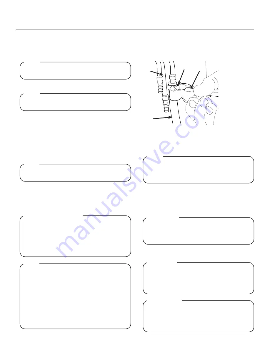
1. Route appropriate tubing from the water source to the plain
water inlet at tower and connect tubing to inlet using the
oetiker pliers and fittings,(see Plumbing Diagram on unit or
page 11 for reference).
Inspect unit for concealed damage. If evident, notify
delivering carrier and file a claim against the same.
NOTE
Selecting/Preparing Counter Location
1. Select a level, well ventilated location that is in close
proximity to a properly grounded electrical outlet, within five
(5) feet (1.5 m) of a drain, a water supply that meets the
requirements shown in the Specifications section found on
page 2, and away from direct sunlight or overhead lighting.
2. The dispenser is designed to be installed permanently to
a counter and must be sealed with a bead of clear silicone
caulk or sealant which provides a smooth and easily
cleanable bond to the counter.
The dispenser should only be installed in a location
where it can be overseen by trained personnel
NOTE
NSF listed units must be sealed to the counter or have
four (4) inch legs installed.
NOTE
To assure that beverage service is accessible to all
customers, Lancer recommends that counter height
and equipment selection be planned carefully. The
2010 ADA Standards for Accessible Design states that
the maximum reach height from the floor should be no
more than 48” if touch point is less than 10” from the
front of the counter, or a maximum of 46” if the touch
point is more than 10” and less than 27” from the front
of the counter. For more information about the
customer’s legal requirements for the accessibility of
installed equipment, refer to 2010 ADA Standards for
Accessible Design - http://www.ada.gov.
NOTE
In order to facilitate proper dispenser drainage, ensure
that the dispenser is level, front to back and side to
side. Place a level on the top of the rear edge of the
dispenser. The bubble must settle between the level
lines. Repeat this procedure for the remaining three
sides. Level unit if necessary. For optimum perfor-
mance place the unit at a 0° tilt. The maximum tilt is 5°.
Leveling the Dispenser:
3. Select a location for the remote chiller systerm, syrup
pumps, CO
2
tank, syrup containers, and water filter
(recommended).
4. Cut out required opening in counter for the water/soda and
syrup lines in the designated dispenser location.
Unit is designed to be supported by a remote chiller
system or remote ice cooled system. Please see the
manufacturer’s specifications and instructions for
installation.
NOTE
6. Connect drain line to fitting at the bottom of the drip tray and
route to designated open type foor drain.
A
B
C
A. Oetiker Pliers
B. Fitting
C. Tubing
D. Syrup/Water
Inlet
D
DO NOT PLUG UNIT INTO GROUNDED ELECTRICAL
OUTLET AT THIS TIME.
Make sure that all water lines
are tight and unit is dry before making any electrical
connections
!
WARNING
4. Route appropriate tubing from the syrup pump location to the
syrup inlets and connect tubing to inlet. Repeat for remaining
syrup lines
5. Route the power supply cord to a grounded electrical outlet
of the proper voltage and amperage rating.
Drain line must be insulated with a closed cell
insulation. Insulation must cover the entire length of
the drain hose, including fittings. The drain should be
installed in such a manner that water does not collect
in sags or other low points, as condensation will form.
!
CAUTION
Pouring hot water down the drain may cause the Drain
Tube to collapse. Allow only luke warm or cold water to
enter the Drain Tube.
Pouring coffee, tea, or other
similar substances down the drain may cause the Drain
Tube to become clogged.
!
ATTENTION
2. Connect tubing to water source then flush water line to check
for leaks.
3. Route appropriate tubing from the remote chiller system
location to the carbonated water inlet on tower and connect
tubing to inlet.


