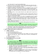
9
2.
Brands
a.
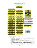
Decide how the brands will be setup.
b.
Choose the
V
alve number (1-2) by scrolling
UP
and
DOWN
arrows.
c.
Use the
LEFT
and
RIGHT
arrows to shift to the
L
eft or
R
ight categories. The
L
eft or
R
ight
categories are set with the assumption that you are looking at them from the front.
d.
Press
UP
and
DOWN
arrows under
L
eft (1-2) or
R
ight (1-2) to select the brand per side
as a single or double. For example, for bezel PN 05-2120, V:1 L:1 R:2
3.
Soda/Water
a.
Decide which switch locations will be carbonated and/or non-carbonated drinks.
b.
Choose the
V
alve number (2-3) by scrolling the
UP
and
DOWN
arrows.
c.
Use the
LEFT
and
RIGHT
arrows to shift to the number categories (
1-4
).
The number
categories correspond to the brand location (per valve) that is being configured.
d.
Press the
UP
and
DOWN
arrows under the number to select if that brand will be
carbonated
S
oda or non-carbonated plain
W
ater. If a single brand per side, only
number
1
and/or
3
need to be set.
3.3
PURGING THE CARBONATION SYSTEM
A. A. Turn power off.
B. Turn the pressure adjusting screw on the CO
2
regulator counter-clockwise, all the way out.
C. The relief valve for the built-in carbonator is located on the right hand side behind the dispenser
splash plate. Lift the yellow lever on the top of the relief valve until water flows from the holes
in the relief valve. Allow pressure on the regulator to drop and then lock the relief valve lever
into place.
D. Turn the pressure adjusting screw on the CO
2
regulator clockwise, until there is resistance.
Open the CO
2
cylinder handle slowly. Turn the CO
2
pressure regulator up (clockwise) slowly to
75 PSIG (5.1 bar).
E. Reconnect the power supply. The remote carbonator pump will activate periodically to fill
carbonator with the appropriate amount of water.
NOTE
To check for CO
2
leaks, close the valve on the CO
2
cylinder and observe if the pressure to the
system drops with the cylinder valve closed for five (5) minutes. Open the cylinder valve after
check.
3.4
PURGING THE WATER AND SYRUP SYSTEMS
A. Open a dispensing valve until water and syrup are flowing steadily from the valve.
B. Repeat procedure "A" for each valve.
C. Check all of the unit's syrup and water connections for leaks and repair if necessary.
D. Replace the unit's splash plate and cup rest.
3.5
ADJUSTING WATER FLOW (
LFCV
®
)
A. The water flow can be adjusted between 2.50 oz/sec (73.9 ml/sec) and 3.75 oz/sec
(110.9 ml/sec) on all dispensing valves using the following procedure.
B. Ice should be on the cold plate for at least one (1) hour before you attempt to brix the valves.
The drink temperature should be no higher than 40°F (4.4°C) when the brix is set.
C. Remove dispenser merchandiser assembly.
D. Rotate switches panel, forward and down by releasing the two pin latches on its sides.
E. Rotate light panel, forward and up by releasing the two pin latches on its sides towards the top.
F.
Remove nozzle by twisting counter clockwise and pulling down.
G. Install Lancer syrup separator (PN 54-0362) in place of nozzle.
H. Activate dispensing valve to fill separator syrup tube.
I.
Hold a Lancer brix cup under the syrup separator and dispense water and syrup into cup for four
(4) seconds. Divide number of ounces (ml) of water in cup by four (4) to determine water flow
rate per second.
J.
To obtain the proper flow, remove protective cap, and use a screwdriver to adjust water flow
control.
K. Repeat process for each "water valve". There can be up to six (6) gray "water valves" on this
dispenser [up to four (4) carbonated "water valves" and two (2) plain "water valves"].


