PAGE 12
6
2
4
3
5
1
7
8
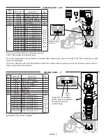
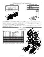
Drawing No.
Order No.
Description
Qty
1
V3176
INJECTOR CAP
1
2
V3152
O-RING 135
1
3
V3177-01
INJECTOR SCREEN CAGE
1
4
V3010-1Z
INJECTOR ASSY Z PLUG
1
5
†
V3010-1C INJECTOR ASSY C VIOLET
1
V3010-1F
INJECTOR ASSY F BLUE
V3010-1H INJECTOR ASSY H GREEN
Not Shown
V3170
O-RING 011
*
Not Shown
V3171
O-RING 013
*
* The injector plug and the injector each contain one 011 (lower) and 013 (upper)
o-ring.
†
Only used with 7-LX125CTAIR and 7-LX125IMAIR Models. For all other models, a
second V3010-1Z injector assy Z plug is used.
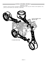
The nut and caps are designed to be unscrewed or tightened by hand or with
the service spanner wrench (see page 16). If necessary a pliers can be used to
unscrew the nut or cap. Do not use a pipe wrench to tighten or loosen nuts or caps.
Do not place a screwdriver in slots on caps and/or tap with a hammer.
Refer to page 20 for detailed service instructions.
1
2
3
4
5
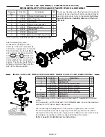
INJECTOR CAP, INJECTOR SCREEN, INJEECTOR, PLUG AND O-RING
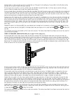
Drawing
No.
Order No.
Description
Qty
1
V3430
Spacer Stack Assembly
1
2
V3004
Drive Cap Assy
1
3
V3178LP
Back Plate
1
4
V3407
Piston Downflow Assy
1
5*
V3174
Regenerant Piston
1
6
V3135
O-ring 228
1
7
V3180
O-ring 337
1
8
V3358
O-ring 219 (Distributor Tube)
1
*Only used with 7-LX125CTAIR and 7-LX125IMAIR models.
DRIVE CAP ASSEMBLY, DOWNFLOW PISTON,
REGENERANT PISTON AND SPACER STACK ASSEMBLY
After completing any valve
maintenance involving the drive
assembly or the drive cap assembly
and pistons, unplug power source jack
from the printed circuit board (black
wire) and plug back in or press and
hold
NEXT
and
REGEN
buttons for 3
seconds. This resets the electronics
and establishes the service piston
position. The display should flash the
software version and then reset the
valve to the service position.
Do not use Vaseline, oils, other hydrocarbon lubricants
or spray silicone anywhere. A silicone lubricant may be
used on black o-rings but is not necessary.
Avoid any
type of lubricants, including silicone, on the clear
lip seals.
†

