16
Call 1-888-370-6531 for Technical Support
Air Pressure:
The burner has a built-in air compressor to provide pressurized air for oil
atomization at the nozzle. The air pressure is set at the factory to 3 - 4 psi. If the pressure
has drifted and a pressure adjustment is required, loosen the 3/8” nut on the bleeder valve,
adjust the stem with a small screwdriver, and tighten the nut to lock it in place. If 3 - 4 psi
cannot be achieved, see Sect. 6.4.4 – Air Compressor Maintenance.
Burn Quality – CO2 Exhaust Measurement:
Only a qualified service technician with an
exhaust combustion analyzer should adjust the burner air shutter. Measurements are taken
through the draft gauge probe port. Exhaust gas carbon dioxide readings should be
approximately 11% ±1% for a clean heater.
The factory setting of the air shutter (75% open) is optimized for average operation, so it
should not normally require adjustment. However, if operating at high-altitude (above 6000
feet), it can be opened fully. To adjust the shutter, loosen the locking screws, then rotate the
shutter and retighten the locking screws.
Burn Quality – Smoke Measurement:
A qualified
service technician may measure smoke content,
following procedures of his smoke pump.
•
Acceptable results per smoke pump
comparison chart = zero or #1 smoke spot.
•
A yellow- brown smoke spot color is normal
when burning used oil due to the presence of non-combustibles.
•
The presence of black or dark grey soot indicates incomplete
combustion.
Flame Monitoring Cad Cell:
The primary control can be used to check the cad cell:
•
The resistance of the flame sensor reduces as it sees brighter light. The flame sensor
should read <1500 Ohms of resistance with the flame burning properly.
•
If the flame looks bright, but the sensor is not responding properly, contact Technical
Support for assistance.
•
To test the flame sensor, disconnect one of the yellow wires at the primary control, start the
burner and then jumper the F1-F2 terminals to keep the burner going. The resistance can
then be measured directly between the two yellow flame sensor wires with a multi-meter on
the ohms setting.
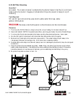
Air Adjustment
Air Pressure
Adjustment
and Gauge
Burner Air
Shutter
Summary of Contents for 81010751
Page 2: ......
Page 41: ...8 Appendices 8 1 Wiring Diagram ...
Page 42: ......
Page 43: ...34 Call 1 888 370 6531 for Technical Support 8 2 Primary Control Instructions ...
Page 44: ...35 Call 1 888 370 6531 for Technical Support Not used with RES 75 kBTU h units ...
Page 45: ...36 Call 1 888 370 6531 for Technical Support No latch up with RES 75 kBTU h units ...
Page 46: ...37 Call 1 888 370 6531 for Technical Support ...


