LAMBORGHINI KYRA D 30 SI UNIT COND Instructions For Use Manual Download Page 7

KYRA D 30 SI UNIT COND

A73022660

40

EN

ATTENTION

In case of a power failure, all settings 
and displays remain stored.

Factory setting activation

The factory setting is activated by pressing and holding the control button and 
deactivating the pump.
•  Press the control button continuously for at least 4 seconds.


-

All LEDs 

fl

 ash for 1 second.


-

The LEDs of the last setting 

fl

 ash for 1 second.

On restarting the pump, it will work with the factory setting (delivery status).

Manual restart

When a blockage is detected, the pump
tries to restart automatically.

If the pump does not restart automatically:

Activate manual restart by pressing the
control button for 5 seconds, then release.


-

The restart function starts and lasts max. 
10 minutes.


-

The LEDs 

fl

 ash clockwise one after the 

other.

To stop, press the control button for 5 sec-
onds.

ATTENTION

After restarting, the LED indicator shows the 
previously set pump values.

If it is not possible to eliminate a fault, con-
tact a system installer or Customer Service

System water characteristics

In case of water with hardness exceeding 25° Fr (1°F = 10ppm CaCO3), use suitably 
treated water to prevent possible encrustations in the boiler. Treatment must not 
reduce the hardness to values below 15°F (Decree 236/88 on water intended for 
human consumption). However, treatment of the water is essential in case of very 
large systems or frequent system water replenishment.

Frost protection system, antifreeze liquids, additives and inhibitors

A frost protection system activates the boiler in heating mode when the system 

fl

 ow temperature drops below 6°C. The device is not active if the power and/or 

gas supply to the unit are disconnected. If necessary, the use of antifreeze liquids, 
additives and inhibitors is allowed, only and exclusively if their manufacturer 
provides a guarantee ensuring that the products are suitable for use and do not 
cause damage to the boiler exchanger or to other components and/or materials of 
the boiler and system. The use of antifreeze liquids, additives and generic inhibitors, 
not speci

fi

 cally suitable for use in heating systems compatible with the boiler and 

system materials, is prohibited.

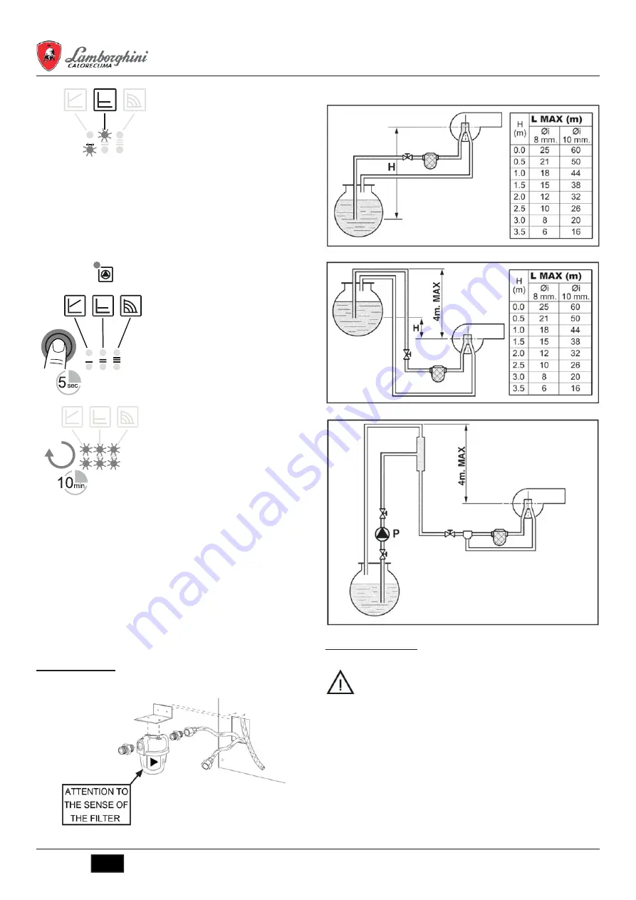
 3.4 Burner connection

The burner is equipped with 

fl

 exible pipes and a 

fi

 lter for connection to the oil feed 

line.Run the 

fl

 exible pipes out of the back and install the 

fi

 lter as indicated in 

fi

 g.20.

fi

 g.18 - Fuel 

fi

 lter installation

The oil feed circuit must be made according to one of the following diagrams, with-
out exceeding the pipe lengths (LMAX) given in the table.

fi

 g.19 -Suction feed

fi

 g.20 - Siphon feed

fi

 g.21 - Ring feed

 3.5 Electrical connections

Connection to the electrical grid

The unit’s electrical safety is only guaranteed when correctly connected 
to anef

fi

 cient earthing system executed according to current safety 

standards. Havethe ef

fi

 ciency and suitability of the earthing system 

checked by professionally quali

fi

 ed personnel. The manufacturer is not 

responsible for any damage caused by failure to earth the system. Also 
make sure that the electrical system is adequate for the maximum power 
absorbed by the unit, as speci

fi

 ed on the boiler dataplate.

The boiler is prewired and provided with a Y-cable and plug for connection to the 
electricity line. The connections to the grid must be made with a permanent connec-
tion andequipped with a bipolar switch whose contacts have a minimum opening of 
at least 3mm, interposing fuses of max. 3A between the boiler and the line. It is im-
portant to respect the polarities (LINE: brown wire / NEUTRAL: blue wire / EARTH:  
yellow-greenwire) in making connections to the electrical line. During installation or 
when changingthe power cable, the earth wire must be left 2 cm longer than the 
others.

Summary of Contents for KYRA D 30 SI UNIT COND

Page 1: ...1 204 63 61 4712 77 13 04 4742 52 20 81 3519 55 03 13 495 268 04 70 8152 59 64 93 8552 20 53 41 831 429 08 12 3843 20 46 81 383 227 86 73 3812 21 46 40 4862 44 53 42 3532 37 68 04 8412 22 31 16 342 20...

Page 2: ...40 3 5 Electrical connections 40 3 6 Connection to the flue 41 3 7 Condensate drain connection 41 4 SERVICE AND MAINTENANCE 41 4 1 Adjustments 41 4 2 Commissioning 43 4 3 Maintenance 44 4 4 Troublesho...

Page 3: ...mplified representation of the product In this representation there may be slight and insignificant differences with re spect to the product supplied 2 OPERATING INSTRUCTIONS 2 1 Introduction Dear Cus...

Page 4: ...C fig 10 DHW temperature adjustment Use the DHW buttons details 1 and 2 fig 1 to adjust the temperature from a min of 10 C to a max of 65 C fig 11 Room temperature adjustment with optional room therm...

Page 5: ...FORMED BY QUALIFIED PER SONNEL IN ACCORDANCE WITH ALL THE INSTRUCTIONS GIVEN IN THIS TECHNICAL MANUAL THE PROVISIONS OF CURRENT LAW THE PRESCRIP TIONS OF NATIONAL AND LOCAL STANDARDS AND THE RULES OF...

Page 6: ...ATTENTION After venting the LED indicator shows the pump set values Set the adjustment mode Select the adjustment mode The LED selection of the adjustment mode and the corresponding characteristic cur...

Page 7: ...nd exclusively if their manufacturer provides a guarantee ensuring that the products are suitable for use and do not cause damage to the boiler exchanger or to other components and or materials of the...

Page 8: ...ore starting the unit Verify Periodically check the water in the trap fig 23 Condensate drain 4 SERVICE AND MAINTENANCE All adjustment conversion commissioning and maintenance operations described bel...

Page 9: ...press the Reset button to access it tS Transparent Parameters Menu The card is equipped with 27 transparent parameters also modifiable from Remote Control Service Menu Index Description Range Default...

Page 10: ...ccurred relevant to Ht H5 Fault code Time fault occurred relevant to Ht H6 Fault code Time fault occurred relevant to Ht H7 Fault code Time fault occurred relevant to Ht H8 Fault code Time fault occur...

Page 11: ...The gas and water systems must be airtight The water pressure in the cold water system must be approx 1 bar otherwise bringit to that value The circulating pump must not be blocked The expansion tank...

Page 12: ...p nozzle Clean Pump unprimed Prime and find the cause of unpriming Ignition electrodes not properly adjusted or dirty Adjust or clean them Nozzle clogged dirty or deformed Replace Unsuitable head and...

Page 13: ...temperature F40 Incorrect system water pressure Pressure too high Check the system Check the safety valve Check the expansion vessel A41 Sensor positioning Delivery sensor not inser ted in boiler shel...

Page 14: ...utomatic air vent 38 Flow switch 42 DHW temperature sensor optional 56 Expansion vessel 74 Charging key 191 Smoke temperature sensor 246 Pressure transducer 275 Key download heating circuit 278 Double...

Page 15: ...iency class according to directive 92 42 CE Max working pressure in heating bar 3 PMS Min working pressure in heating bar 0 8 Max heating temperature C 80 tm x Heating water content liters 49 Heating...

Page 16: ...emperature regime 1 97 5 Auxiliary electricity consumption At full load elmax kW 0 188 At part load elmin kW 0 075 In standby mode PSB kW 0 003 Other items Standby heat loss Pstby kW 0 100 Ignition bu...

Page 17: ...3 204 51 73 343 384 55 89 4932 77 34 06 3412 26 03 58 395 279 98 46 843 206 01 48 4012 72 03 81 4842 92 23 67 3842 65 04 62 8332 68 02 04 861 203 40 90 391 204 63 61 4712 77 13 04 4742 52 20 81 3519 5...

Reviews: