


39
- checking general external appearance of boiler
- checking for proper ignition, shutdown and operation of both hot water and heating functions
- checking for proper seal on gas/water fittings and pipes.
- checking gas consumption at minimum and maximum power
- checking position of ignition electrode
- checking position of detection electrode
- checking combustion and efficiency parameters
- checking the no-gas safety device
- checking combustion fumes outlet safety device
- water system pressure
- expansion tank efficiency
- checking for proper operation of safety and adjustment thermostats
- checking for proper circulation pump operation
- checking that no gas whatsoever leaks from the unit and no combustion gas leaks from the down-
draught diverter or the boiler-flue connection.
- checking gas flow rate.
Do not
clean the unit and/or its component parts with easily inflammable substances (e.g. petrol,
alcohol etc.)
Do not
clean panelling, painted and plastic parts with paint diluents.
Clean the panelling with soapy water only.
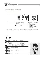
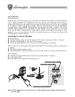
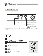
KNOB ASSEMBLY INSTRUCTIONS
If the electronic display board (A) is replaced, the knobs and the control board must be correctly positioned
during reassembly.
Before reassembling the new display board, zero set the potentiometers (trimmers) by turning anticlockwise as
illustrated in the figure:
R05
R04
R2
R1
P2
R01
R02
R03
LD1
R5
P1
P3
LD2
LD3
J1
U1
R3
R4
R6
Turn the trimmers to zero set.
Red Led
Green Led
Yellow Led
(A)
Potentiometers


